Suspension type monorail vehicle coupling dynamic simulation system and method

A technology of coupled dynamics and simulation system, which is applied in the field of coupled dynamics simulation system of suspended monorail vehicles, and can solve the problems of large errors in simulation results

Active Publication Date: 2018-07-06
SOUTHWEST JIAOTONG UNIV
View PDF3 Cites 31 Cited by
  • Summary
  • Abstract
  • Description
  • Claims
  • Application Information

AI Technical Summary

Problems solved by technology

[0007] The purpose of the present invention is to provide a suspended monorail vehicle coupling dynamics simulation system and its simulation method in order to solve the technical problem that the existing suspended monorail dynamics simulation device has a large error in the simulation results when studying the local vibration of the track beam

Method used


Image

  • Suspension type monorail vehicle coupling dynamic simulation system and method
  • Suspension type monorail vehicle coupling dynamic simulation system and method
  • Suspension type monorail vehicle coupling dynamic simulation system and method

Examples


Embodiment 1

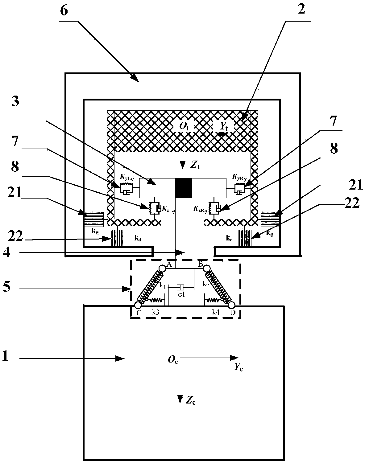
[0099] A coupled dynamics simulation system for suspended monorail vehicles, the simulation system is mainly used for dynamic simulation of suspended monorail vehicles. The simulation system includes a track beam, which includes a track beam top plate, a track beam web, and a track beam bottom plate. There are two sets of track beam webs, and the two sets of track beam webs are connected on the left , On the right side, the track beam roof and track beam web are connected to form a "П" structure. Track beam bottom plates are arranged on the inner side walls of the two sets of track beam webs, and the two sets of track beam bottom plates are arranged parallel to the track beam top plate, and the sum of the widths of the two sets of track beam bottom plates is smaller than the width of the track beam top plate, so that the left There is a certain distance between the track beam bottom plate on the right side and the track beam bottom plate on the right side. A bogie is also arr...

Embodiment 2

[0102] On the basis of the first embodiment, a suspension mechanism model is also provided, and the central pin is connected with the vehicle body through the suspension mechanism model.

Embodiment 3

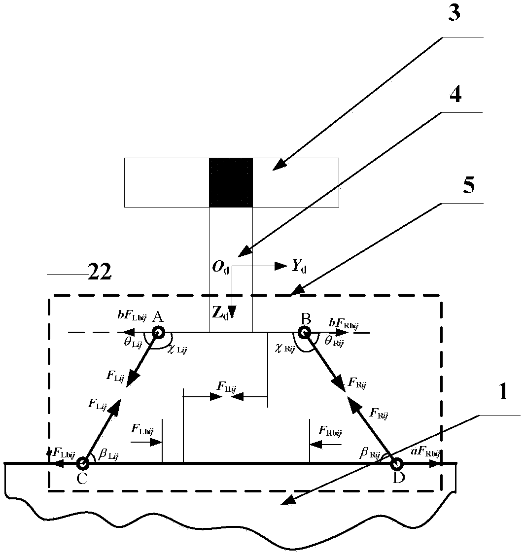
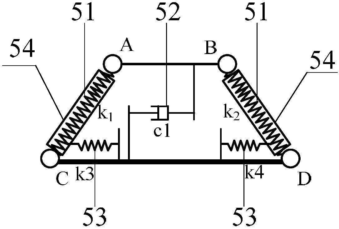
[0104] On the basis of the second embodiment, a specific suspension mechanism model is provided. The suspension mechanism model includes two sets of cable-stayed spring models set in a "eight"-shaped mirror image. Side connection, point B at the upper end and point D at the lower end of the right side cable-stayed spring model are respectively connected to the right side at the bottom of the center pin and the right side at the top of the car body. Each group of inclined-stay spring models is equipped with a pull rod sleeve, and the end of each set of pull rod sleeves close to point C or D is connected to the top of the car body through the first elastic stopper model, and the bottom of the center pin and the top of the car body The equivalent model of the first transverse shock absorber is also connected between them. The equivalent model of the first transverse shock absorber is set perpendicular to the line between the central pin and the vehicle body.


PUM


Abstract

The invention discloses a suspension type monorail vehicle dynamic model and a vehicle-bridge coupling power simulation method, belongs to the technical field of rail traffic and aims to solve the technical problem that an existing suspension type monorail dynamics simulation device is large in simulation result errors during rail beam local vibration research. By providing the suspension type monorail vehicle system dynamic model, a rubber wheel-rail surface contact mechanical model, a rail beam bottom plate and web equivalent surface force application method and a vehicle and rail beam coupling dynamic model building method, a suspension type monorail vehicle-rail beam coupling dynamic simulation system is built. By the model, the system and the method, suspension type monorail vehicle system suspension mechanism decoupling and equivalent treatment are achieved, and the technical problems that the existing suspension type monorail dynamics simulation device is large in simulation result errors during the rail beam local vibration research, rail beam dynamic stress and strain results are hard to extract, rail beam local strength destroying cannot be evaluated accurately and the like are solved.

Description

technical field [0001] The invention belongs to the technical field of rail transit, and relates to a suspension type monorail vehicle coupling dynamics simulation system and a simulation method thereof. Background technique [0002] Suspended monorail transit is a new type of rail transit system. It has the advantages of strong climbing ability, small curve passing radius, low cost, low noise, short construction period, and small footprint. It can meet short-distance and small-to-medium passenger flow transportation tasks. Suspended monorail transportation is suitable for the extension and connecting lines of the secondary and main lines of public transportation in large cities, the main public transportation lines of small and medium-sized cities, the connecting lines from airports, high-speed rail, and intercity railway stations to the city center or scenic spots, and large-scale natural tourist attractions Lines and intra-area connecting lines and other ranges. [0003...

Claims


Application Information

Patent Timeline
Patent Type & Authority Applications(China)
IPC IPC(8): G06F17/50
CPCG06F30/20G06F2119/06Y02T90/00
Inventor 何庆烈蔡成标朱胜阳翟婉明王明昃尹镪陈兆玮张嘉伟杨尚福徐翔
Owner SOUTHWEST JIAOTONG UNIV
Why Eureka
Try Eureka