
Source drive circuit and liquid crystal display drive circuit

A source drive and circuit technology, applied in static indicators, instruments, etc., can solve problems such as the inability to meet the compatibility requirements of the source drive drive circuit, the inability to meet the image quality requirements of liquid crystal displays, etc., to improve compatibility, improve The effect of the number of grayscales

Inactive Publication Date: 2018-07-06
SHENZHEN CHINA STAR OPTOELECTRONICS TECH CO LTD
View PDF15 Cites 3 Cited by
  • Summary
  • Abstract
  • Description
  • Claims
  • Application Information

AI Technical Summary

Problems solved by technology

The number of gray scales of the existing source drive circuit can no longer meet the image quality requirements of the existing liquid crystal display
Moreover, only one receiver can no longer meet people's requirements for the compatibility of source drive circuits.

Method used


Image

  • Source drive circuit and liquid crystal display drive circuit
  • Source drive circuit and liquid crystal display drive circuit
  • Source drive circuit and liquid crystal display drive circuit

Examples


Embodiment Construction

[0026] Embodiments of the present invention are described in detail below, examples of which are shown in the drawings, wherein the same or similar reference numerals denote the same or similar elements or elements having the same or similar functions throughout. The embodiments described below by referring to the figures are exemplary only for explaining the present invention and should not be construed as limiting the present invention.

[0027] In describing the present invention, it is to be understood that the terms "center", "longitudinal", "transverse", "length", "width", "thickness", "upper", "lower", "front", " Orientation indicated by rear, left, right, vertical, horizontal, top, bottom, inside, outside, clockwise, counterclockwise, etc. The positional relationship is based on the orientation or positional relationship shown in the drawings, which are only for the convenience of describing the present invention and simplifying the description, rather than indicating ...


PUM


Abstract

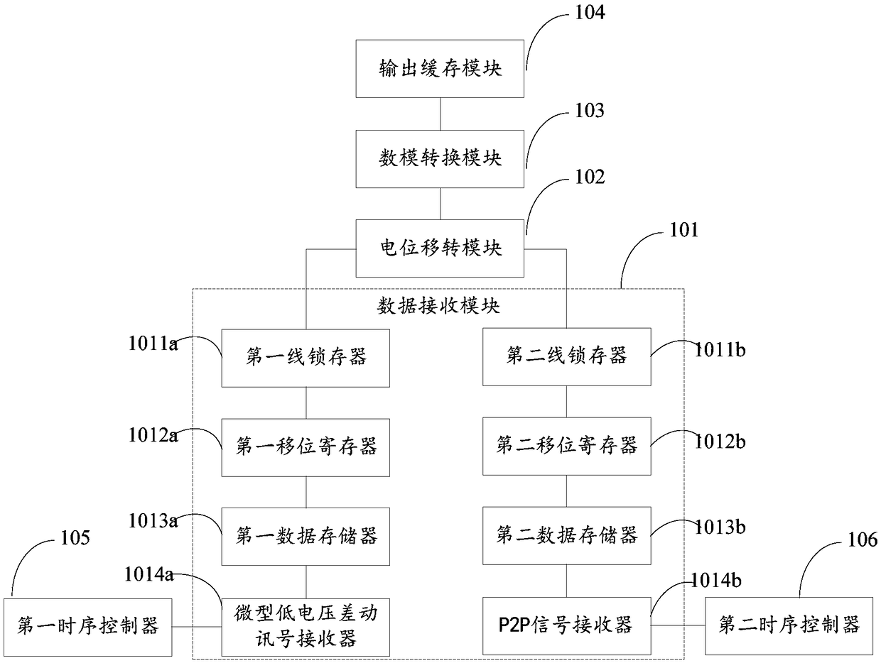
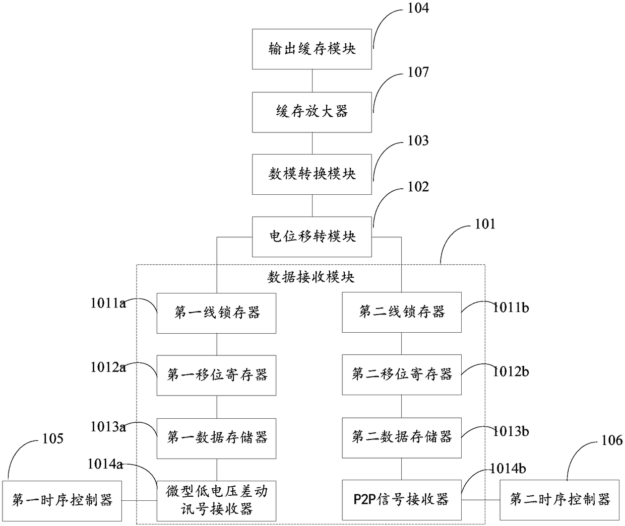
The invention provides a source drive circuit. The source drive circuit comprises a data receiving module, a potential transfer module, a digital-analog conversion module and an output buffer module which are connected in sequence. The data receiving module comprises a first wire latch, a second wire latch, a first shifting register, a second shifting register, a first data storage device, a second data storage device, a first time schedule controller, a second time schedule controller, a mini-low voltage differential signal receiver and a P2P signal receiver; the first wire latch, the first shifting register, the first data storage device and the mini-low voltage differential signal receiver are connected in sequence, the second wire latch, the second shifting register, the second data storage device and the P2P signal receiver are connected in sequence, the first wire latch and the second wire latch are connected with the potential transfer module separately, the first time schedulecontroller is connected with the mini-low voltage differential signal receiver, and the second time schedule controller is connected with the P2P signal receiver.

Description

technical field [0001] The invention relates to the field of liquid crystal display, in particular to a source drive circuit and a liquid crystal display drive circuit. Background technique [0002] In the current TFT-LCD driving circuit, the source driver is receiving mini-LVDS (miniature low voltage differential signal receiver) or receiving P2P (point-to-point) receiver. The number of gray scales of the existing source driving circuit can no longer meet the image quality requirements of the existing liquid crystal display. Moreover, only using one kind of receiver can no longer meet people's requirements on the compatibility of the source driving circuit. [0003] Therefore, there are defects in the prior art, and improvement is badly needed. Contents of the invention [0004] The purpose of the embodiments of the present invention is to provide a source driving circuit and a liquid crystal display driving circuit, which can improve image quality. [0005] A source d...

Claims


Application Information

Patent Timeline
Patent Type & Authority Applications(China)
IPC IPC(8): G09G3/36
CPCG09G3/3688
Inventor 黎云涛
Owner SHENZHEN CHINA STAR OPTOELECTRONICS TECH CO LTD
Learn More