
Power relay plastic assembly

A power relay, plastic technology, applied in relays, electromagnetic relays, electromagnetic relay detailed information and other directions, can solve the problems of many production organization processes, short service life, complicated assembly positioning, etc., to improve creepage distance and insulation performance, improve Creepage distance and insulation, the effect of avoiding excessive pull-in voltage

Pending Publication Date: 2018-07-06
YUEQING MEISHUO ELECTRIC
View PDF0 Cites 0 Cited by
  • Summary
  • Abstract
  • Description
  • Claims
  • Application Information

AI Technical Summary

Problems solved by technology

[0003] With the development of electrical miniaturization, traditional relays have large volume, relatively large base, push rod and coil frame, and the combination with functional parts is not compact enough, and the separation between the magnetic circuit system and the conductive system of the relay is not clear enough. The insulation of the coil is not high enough; the assembly and positioning of each component is complicated, and there are many production organization procedures, mainly manual assembly and semi-automatic assembly, which cannot meet the needs of fast and efficient industrial automation manufacturing; , the shrapnel rebounds and is easy to pull the push rod to move back quickly, causing the relay to fail, the service life is short, and sometimes there are faults such as broken enameled wire between the coil and the lead pin, which affects the normal use and life of the product

Method used


Image

  • Power relay plastic assembly
  • Power relay plastic assembly
  • Power relay plastic assembly

Examples


Embodiment Construction

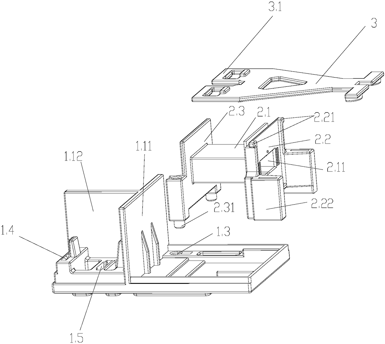
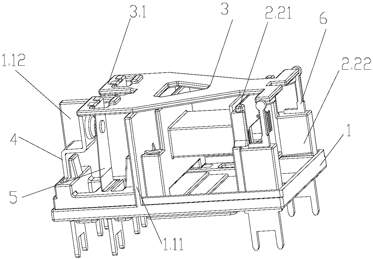
[0023] The power relay plastic assembly provided by the embodiment of the present invention has a compact structure and a small volume. Through the rational layout of the base 1, the coil frame 2 and the push rod 3, the creepage distance and insulation of the relay are improved, and the relay is effectively prevented from being caused by excessive pull-in voltage. The work is invalid, and the assembly positioning is convenient, the precision is high, and it is convenient for automatic assembly.

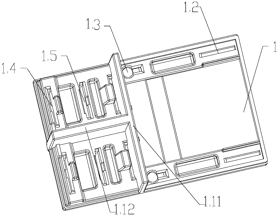
[0024] Such as figure 1 , figure 2 As shown, the plastic assembly of the power relay in this embodiment includes a base 1, a coil frame 2 and a push rod 3, wherein the base 1 is provided with a "T-shaped" insulating wall 1.1, which divides the base into a conductive system area and a magnetic circuit system The magnetic circuit system area is symmetrically provided with lead foot mounting holes 1.2 and positioning grooves 1.3 on the front and rear sides. The positioning shaft 2.31 o...


PUM


Abstract

The invention discloses a power relay plastic assembly, which comprises a base, a coil frame and a push rod, wherein a T-shaped insulation wall is arranged on the base, the base is segmented to a conductive system area and a magnetic circuit system area, a lead pin mounting hole and a positioning groove are symmetrically arranged at the front side and the rear side of the magnetic circuit system area, a positioning shaft of an H-shaped coil frame is inserted in the positioning groove of the base, the lower part of a right bottom plate of the coil frame is provided with a pair of rectangular lead pin seats and each of two vertex angles of the upper part of the right bottom plate is provided with a convex wire clamping bolt, a dynamic spring mounting hole and a static spring mounting hole are symmetrically arranged in the conductive system area of the base, acting plates with dynamic spring ports are symmetrically arranged in the front part and the rear part of the acting end of the pushrod, and a limiting block is vertically arranged on the back surface of the acting plate. According to the power relay plastic assembly, the structure is compact and novel, the size is small, and through rational layout among the base, the coil frame and the push rod, the creepage distance and the insulation of the relay are improved, excessive pull-in voltage to cause relay failure can be effectively avoided, the assembly and the positioning are convenient, and the precision is high.

Description

technical field [0001] The invention relates to a small electromagnetic relay, in particular to a plastic component of a power relay, and belongs to the technical field of electrical equipment. Background technique [0002] Electromagnetic relay is a kind of relay that uses electromagnetic force to drive the relative movement of mechanical parts to produce a predetermined response. It is generally composed of iron core, coil, armature, yoke, shrapnel, push rod, and dynamic and static spring with contacts. When the current passes through the coil, electromagnetic force is generated, and the armature is attracted, so that the moving contact of the moving spring contacts the static contact of the static spring; when the current in the coil disappears, the electromagnetic force disappears, and the armature resets, so that the moving contact The moving contact of the spring is separated from the static contact of the static spring, and the purpose of conducting or cutting off the...

Claims


Application Information

Patent Timeline
Patent Type & Authority Applications(China)
IPC IPC(8): H01H50/02H01H50/44H01H50/64
CPCH01H50/02H01H50/44H01H50/642H01H2050/028H01H2050/446
Inventor 孙晓志方旭陈海多彭碧辉卿新华朱军黄晓湖虞彭鑫
Owner YUEQING MEISHUO ELECTRIC
Learn More