Six-pole plate applied to capacitive wireless charging system

A wireless charging and capacitive technology, applied to electrical components, circuit devices, etc., can solve problems such as increasing system complexity

Pending Publication Date: 2018-07-06
开沃新能源汽车集团股份有限公司
View PDF3 Cites 5 Cited by
  • Summary
  • Abstract
  • Description
  • Claims
  • Application Information

AI Technical Summary

Problems solved by technology

However, this approach increases system complexity and requires real-time control of multiple pairs of plates

Method used


Image

  • Six-pole plate applied to capacitive wireless charging system
  • Six-pole plate applied to capacitive wireless charging system
  • Six-pole plate applied to capacitive wireless charging system

Examples


Embodiment Construction

[0030] The present invention will be further described below in conjunction with the accompanying drawings and specific embodiments.

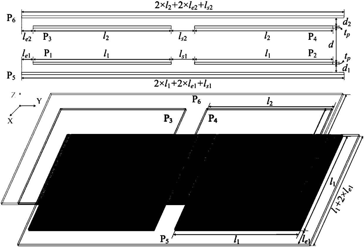
[0031] The structure of the six-pole plate is as figure 1 shown. Plate P 1 ,P 2 and P 5 Placed on the primary side as the sending end, the plate P 3 ,P 4 and P 6 Placed on the secondary side as the receiver. Plate P 1 ,P 2 ,P 3 and P 4 It is the main power plate, which is responsible for power transmission. Plate P 5 and P 6 It is the shielding plate, which is responsible for reducing the external electric field radiation, and their size is much larger than that of the main power plate for better shielding effect. The definitions of the dimensions of the electrode plates are shown in Table 1. It should be emphasized that in general applications, the shape of the electrode plate can be changed according to actual needs, and it does not have to be square. Moreover, in practice, there may be size differences between the primary sid...


PUM


Abstract

The invention provides a novel six-pole plate type coupling structure for a capacitive wireless charging system, so as to reduce electric field radiation to the external environment. The six-pole plate comprises six electrode plates, wherein four of the electrode plates are used for transmitting power, and the other two are used as shielding pole plates for reducing the electric field radiation tothe external environment. In the six-pole plate structure, a coupling capacitor exists between every two electrode plates, a total of 15 coupling capacitors are arranged, and the difficulty of analyzing a pole plate model and circuit performance is increased. The invention provides a novel three-port model, which can be further simplified into a two-port model for analyzing the working process ofa circuit. The finite element analysis based on Maxwell proves that the six-pole plate structure can effectively reduce the electric field radiation, and the safety range is increased from 0.6 meteraway from the six-pole plate to 0.1 meter away from the six-pole plate. The experimental results show that when an air gap distance is 150 mm, the efficiency from input DC power supply to output loadreaches 91.6%.

Description

technical field [0001] The invention relates to the field of electric vehicle charging, in particular to a six-pole plate applied to a capacitive wireless charging system. Background technique [0002] Capacitive wireless charging technology uses alternating electric fields instead of magnetic fields to transmit energy, which is an important supplement to inductive wireless power transmission. Compared with inductive power transmission, capacitive power transmission has three advantages. One is that the alternating electric field will not cause eddy current loss in nearby metal objects, will not cause temperature rise and potential fire hazards, so it is safer. Second, capacitive power transmission uses metal plates as the electric field coupling structure, which reduces the use of expensive high-frequency Litz wires and magnetic materials in the system, and greatly reduces the overall cost of the system. The third is that the displacement capability of the capacitive wire...

Claims


Application Information

Patent Timeline
Patent Type & Authority Applications(China)
IPC IPC(8): H02J50/05H02J50/70
CPCH02J50/05H02J50/70
Inventor 黄福良吴飞崔小慧樊文堂张蒙阳
Owner 开沃新能源汽车集团股份有限公司
Why Eureka
Try Eureka