Full-automatic cleaning system and cleaning method of photovoltaic module

A photovoltaic module and cleaning system technology, applied in the field of cleaning systems, can solve the problems of large number of photovoltaic factory areas, shading, and wasteful use of cleaning robots, and achieve the effects of real-time unmanned cleaning, reduced pressure unevenness, and strong ability to overcome obstacles

Inactive Publication Date: 2018-07-06
武汉协鑫新能源电力设计有限公司
View PDF4 Cites 5 Cited by
  • Summary
  • Abstract
  • Description
  • Claims
  • Application Information

AI Technical Summary

Problems solved by technology

[0005] 2. In terms of cleaning effect: due to the generally large area of ​​the photovoltaic factory area, it is difficult for workers to control the cleanliness of the components during the cleaning process. Different operators have different forces and different pressures on the components, which will cause excessive deformation of the components and cause battery chips Cracks, another disadvantage is that the effect of dry-cleaning components is not good, often due to too much dust on the mop, there are some traces on the surface of the components, resulting in large areas of shadows
[0006] 3. In terms of cost: cleaning workers use long-handled velvet mop and special detergent for cleaning. The working cycle of dry cleaning is about 3 days/10MW, and the cost is about 12,000-13,000 yuan/10MW/time, which is relatively high.
[0007] (2) Defects and deficiencies in artificial water washing components
In many photovoltaic factories in the northwest and mountainous areas, there is a shortage of water sources, so it cannot be used on a large scale
[0009] 2. In terms of cleaning effect: when the water pressure is too high on the photovoltaic module, it will cause the cells to crack, and we cannot control the change of the water pressure of the operator's nozzle during the process, because the higher the water pressure, the better th...

Method used


Image

  • Full-automatic cleaning system and cleaning method of photovoltaic module
  • Full-automatic cleaning system and cleaning method of photovoltaic module

Examples


Embodiment Construction

[0034] The present invention will be further described below in conjunction with specific embodiments. The following examples are only used to illustrate the technical solution of the present invention more clearly, but not to limit the protection scope of the present invention.

[0035] Below in conjunction with accompanying drawing and embodiment the patent of the present invention is further described.

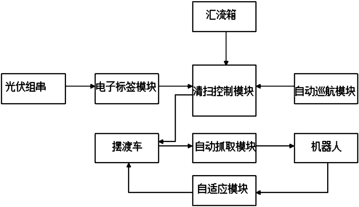
[0036] Such as figure 1 As shown, the present invention provides a fully automatic cleaning system for photovoltaic modules, including a shuttle bus, a robot, an adaptive module, an electronic label module, a cleaning control module and an automatic grabbing module;

[0037] The electronic label module is used to collect the position coordinates of each row and row of photovoltaic strings in the photovoltaic power station, and upload them to the cleaning control module;

[0038] The cleaning control module judges whether the photovoltaic string needs to be cleaned by coll...


PUM


Abstract

The invention provides a full-automatic cleaning system and a cleaning method of a photovoltaic module. The full-automatic cleaning system comprises a shuttle bus, a robot, a self-adaptive module, anelectronic label module, a cleaning control module and an automatic grabbing module; the electronic label module is used for collecting position coordinate of every line and every row of photovoltaicstring of a photovoltaic power station, and uploading to the cleaning control module; the cleaning control module judges if the photovoltaic string is required to clean through every branch current inevery junction box in the photovoltaic array and comparing with the reference current; if it requires, sending the position information of the photovoltaic string to the shuttle bus through the cleaning control module; grabbing the cleaning robot through the automatic grabbing module after the shuttle bus confirms the robot location through the self-adaptive module, and sending the robot to the photovoltaic string position required to clean according to the position information sent by the cleaning control module.

Description

technical field [0001] The invention relates to a cleaning system, in particular to a photovoltaic module automatic cleaning system and a cleaning method. Background technique [0002] The natural environment of large-scale ground photovoltaic power station construction areas in China is harsh, and the cleaning and maintenance methods are backward. The actual output power of photovoltaic systems is seriously affected by dust and fouling, especially in the main photovoltaic construction areas in Northwest China; therefore, the problem of dust disposal of photovoltaic modules needs to be solved urgently . At present, photovoltaic modules mainly adopt four methods: manual dry cleaning, manual water washing, engineering vehicle cleaning, and cleaning robot cleaning: [0003] (1) Defects and deficiencies in manual dry cleaning components [0004] 1. Implementation: In the process of manual dry cleaning, there will be problems such as labor-intensive and construction difficultie...

Claims


Application Information

Patent Timeline
IPC IPC(8): H02S40/10
CPCH02S40/10Y02E10/50
Inventor 朱恺之吴洪宽蔡光德焦晓雷马彰勋
Owner 武汉协鑫新能源电力设计有限公司
Why Eureka
Try Eureka