Intelligent wiper and work condition automatic recognition and protection method thereof

A floor mopping machine, an intelligent technology, applied in manual floor scrubbing machinery, carpet cleaning, floor cleaning, etc., can solve the problems of personnel or the ground, floor mopping machine damage, time-consuming and laborious, poor safety and reliability, etc., and achieves the level of intelligence Good, easy to use, simple effect

Active Publication Date: 2018-07-10
NINGBO SAWADIKA ELECTRICAL APPLIANCE
View PDF10 Cites 7 Cited by
  • Summary
  • Abstract
  • Description
  • Claims
  • Application Information

AI Technical Summary

Problems solved by technology

[0003] The present invention mainly provides an intelligent floor mopping machine with simple structure, safety and reliability, which can automatically detect and identify the state of the floor mopping machine, and control the floor mopping machine to perform related actions according to the detected state, and its working state automatic identification and protection method to solve the problem of The smart floor mopping machine existing in the prior art needs to turn off the power switch in the working conditions such as changing the mop, which is not only time-consuming and laborious, but also easily leads to damage to personnel, the ground, and the floor mopping machine in the case of misoperation, poor safety and reliability, etc. technical issues

Method used


Image

  • Intelligent wiper and work condition automatic recognition and protection method thereof
  • Intelligent wiper and work condition automatic recognition and protection method thereof
  • Intelligent wiper and work condition automatic recognition and protection method thereof

Examples


Embodiment

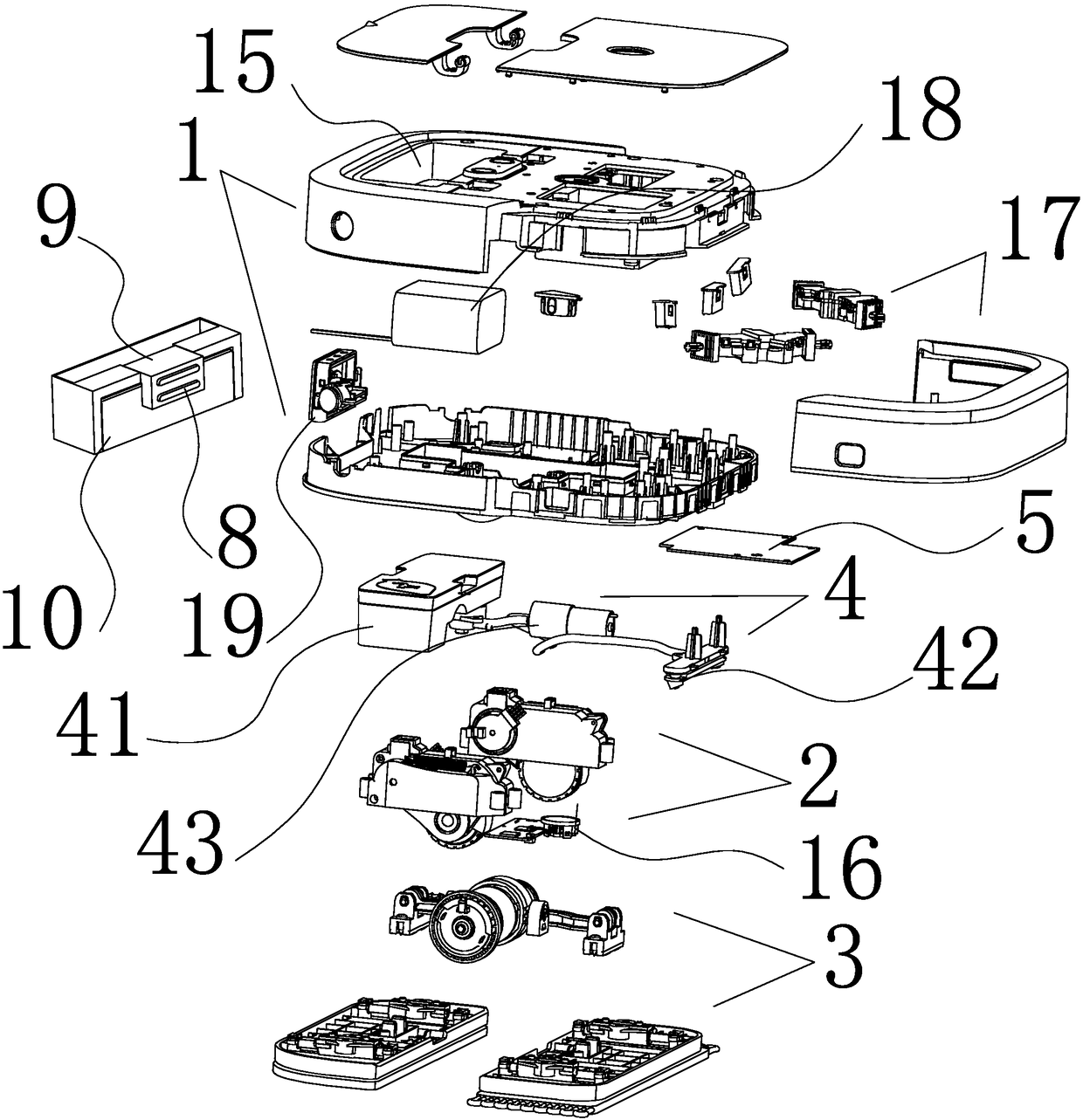
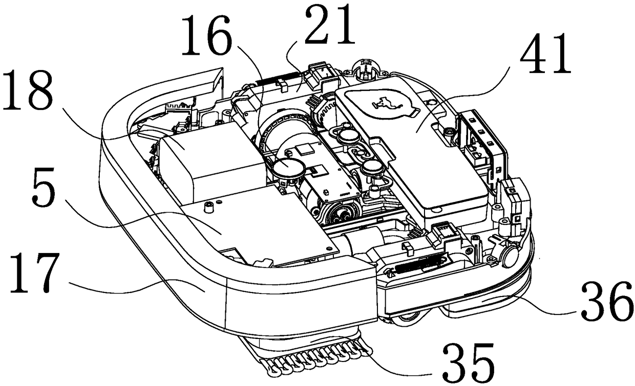
[0033] like figure 1 and figure 2 As shown, an intelligent mopping machine of the present invention includes a housing 1 spliced ​​by upper and lower housings, and a wiping movement system 3 and a walking system 2 connected to a controller 5 are installed in the housing 1 , water spray system 4 and anti-collision system 17, charging system 19, visual navigation system 16 and battery 18, etc., anti-collision system 17 is located at the front side of housing 1, charging system 19 is located at the rear side of housing 1, and visual navigation system 16 is located at In the middle of the housing 1, the accumulator 18 and the controller 5 are located between the anti-collision system 17 and the visual navigation system 16, and the water spray system 4 is located between the visual navigation system 16 and the charging system 19. A pair of wheel power assemblies 21 in the casing 1, the two wheel power assemblies 21 are symmetrically arranged on the left and right sides of the wip...


PUM


Abstract

The invention discloses a wiper and provides an intelligent wiper which is safe and reliable and can automatically detect and recognize the work condition of the wiper and can be controlled to carry out related operation according to the detected condition and a work condition automatic recognition and protection method, which solves the technical problems in the prior art that when the power supply is turned off under the condition of replacing the mop, etc., users or the ground or the wiping machine are easily damaged caused by misoperations. The intelligent wiper comprises a housing, a wipecloth moving system and a walking system which are installed inside the housing; the walking system comprises a wheel set power assembly with one end being rotationally connected to the housing and the other end of the wheel set power assembly extends out from the housing and is supported on the ground through the roller; an optical coupler groove is installed inside the housing corresponding tothe wheel set power assembly; the optical coupler groove is connected to the controller; the wheel set power assembly corresponding to the optical coupler groove is provided with a raster sheet whichextends to the U-shaped opening of the optical coupler groove; the controller controls the working state of the wiper according to the detection signals of the raster sheet by the optical coupler groove.

Description

technical field [0001] The invention relates to a floor mopping machine, in particular to an intelligent floor mopping machine which is simple in structure, safe and reliable, and can automatically detect and identify the state of the floor mopping machine, and control the floor mopping machine to perform related actions according to the detected state, and its working state automatic Identify protection methods. Background technique [0002] The traditional way of cleaning the ground is to use a mop. The process is completely dependent on manpower, and the labor intensity is high. In order to save physical strength and reduce people's labor, people have developed various intelligent automatic mopping machines, usually through the main machine. The motor drives the two mop cloths at the bottom to reciprocate and horizontally move to wipe the ground. When changing the mop cloth, it is often necessary to turn off the power switch of the intelligent floor mopping machine first,...

Claims


Application Information

Patent Timeline
Patent Type & Authority Applications(China)
IPC IPC(8): A47L11/28A47L11/40
CPCA47L11/28A47L11/4008A47L11/4011A47L11/4061A47L11/4088A47L2201/02A47L2201/06
Inventor 陈锵锵
Owner NINGBO SAWADIKA ELECTRICAL APPLIANCE
Why Eureka
Try Eureka