Laser pipe cutting chuck signal control device

A signal control and laser cutting technology, which is applied to laser welding equipment, manufacturing tools, tubular objects, etc., can solve the problems of low production tempo, low degree of automation, and low efficiency, so as to reduce labor intensity, improve automation, and improve intelligence. Effect

Pending Publication Date: 2018-07-10
FOSHAN HONGSHI LASER TECH CO LTD
View PDF6 Cites 3 Cited by
  • Summary
  • Abstract
  • Description
  • Claims
  • Application Information

AI Technical Summary

Problems solved by technology

The current mainstream laser pipe cutting chuck does not have a jaw signal feedback device, because the chuck is a rotating body, some common methods, such as installing proximity switches or sensors on the chuck, cannot be implemented, because the chuck cannot be rotated. The body provides power and signal wiring, so the existing laser tube cutting machine has the following disadvantages:
[0003] 1. It does not detect the jaw signal of the chuck, and it is completely inconvenient to use to confirm whether the chuck is opened or closed, etc.
The degree of automation is low, which increases the labor intensity of operators;
[0004] 2. When the pipe cutting machine cooperates with the automatic feeding system, the current method is to use the delay to do it; in this way, there is generally no problem in the normal use of the chuck; but if it needs to be stuck in the process of feeding the pipe The disc is opened; in fact, the chuck is not opened due to a fault, and if the operator does not find out in time, the chuck will be damaged;
[0005] 3. Another point of using the delay control method is to leave a relatively long reaction time to ensure that there is enough time for the chuck to open or clamp; this is a waste of time for the joint automatic feeding system. The production takt will be much lower and the efficiency will not be high

Method used


Image

  • Laser pipe cutting chuck signal control device
  • Laser pipe cutting chuck signal control device
  • Laser pipe cutting chuck signal control device

Examples


Embodiment Construction

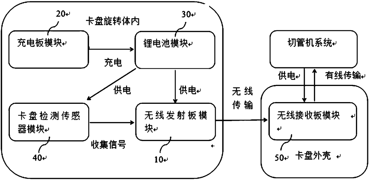
[0022] Such as figure 1 As shown, a kind of cutting pipe chuck signal control device includes: including a wireless launch board module (the main control chip is a 32-bit ARM Cortex-M0 microprocessor bit as the core integrated wireless transmitter and ADC, etc.) 10, a charging board Module 20, battery module 30, chuck detection sensor module 40 and wireless receiving board module (32-bit ARM Cortex-M0 microprocessor is the core integrated hard decoding wireless receiver) 50, preferably, battery module 30 is a lithium battery module . Wherein, the charging board module 20, the lithium battery module 30, the wireless transmitting board 01 module and the chuck detection sensor module 40 are arranged in the rotating body of the chuck, the wireless receiving board module 50 is arranged on the chuck shell, and the lithium battery module 3 is a wireless The launch board module 1 and the chuck detection sensor module 40 provide power; the charging board module 20 provides a charging ...


PUM


Abstract

The invention provides a laser pipe cutting chuck signal control device. A charging panel module, a lithium battery module, a wireless transmission plate module and a chuck detection sensor module arearranged in a rotary body of a chuck. A wireless receiving plate module is arranged on a shell of the chuck. The laser pipe cutting chuck signal control device can automatically and effectively achieve state detection of the chuck, transmit the chuck state to a pipe cutting machine upper system. The pipe cutting machine upper system can make working arrangement according to the received chuck information. Intellectualization and automation of equipment can be improved. The safety protection of the chuck is greatly improved. The additional value of the chuck is increased. The labor intensity of operating workers can be reduced.

Description

technical field [0001] The invention relates to the field of laser pipe cutting machines, in particular to a laser pipe cutting chuck signal control device. Background technique [0002] In the laser pipe cutting machine, the automatic chuck is a very important part. The chuck can be automatically opened, clamped, and the pipe can be clamped for rotary processing. Now the mainstream laser pipe cutting chuck does not have a jaw signal feedback device, because the chuck is a rotating body, some common methods, such as installing proximity switches or sensors on the chuck, cannot be implemented, because the chuck cannot be rotated. The body provides power and signal wiring, so the existing laser tube cutting machine has the following disadvantages: [0003] 1. It does not detect the jaw signal of the chuck, and it is very inconvenient to use by people to confirm whether the chuck is opened or closed. The degree of automation is low, which increases the labor intensity of ope...

Claims


Application Information

Patent Timeline
Patent Type & Authority Applications(China)
IPC IPC(8): B23K26/70B23K26/38B23K101/06
CPCB23K26/38B23K26/702
Inventor 何永强常勇
Owner FOSHAN HONGSHI LASER TECH CO LTD
Why Eureka
Try Eureka