High-temperature-resistant combined type sinking roll

A combined, high-temperature-resistant technology, used in coatings, metal material coating processes, hot-dip plating processes, etc., can solve the problems of time-consuming disassembly, poor structural strength, and poor rigidity, and achieve corrosion resistance and wear resistance. The effect of improving properties, improving strength and rigidity, and good thermal fatigue resistance

Inactive Publication Date: 2018-07-10
孙颖
View PDF5 Cites 1 Cited by
  • Summary
  • Abstract
  • Description
  • Claims
  • Application Information

AI Technical Summary

Problems solved by technology

[0002] The sinking roller on the existing hot-dip galvanizing device generally includes a roller, two roller shafts, and two connecting bushings. The connecting bushings have a stepped structure, and the big end is a flange. The connecting shaft sleeve flange is fixedly connected; the small end of the connecting shaft sleeve is set on one end of the roller shaft and fixedly connected. The main defects of this type of sinking roller are: first, the structural strength and rigidity are poor; Swirl flow is formed when circulating in the inner cavity of the roller; the third is that the assembly or disassembly of the roller and the connecting sleeve is time-consuming and troublesome

Method used


Image

  • High-temperature-resistant combined type sinking roll
  • High-temperature-resistant combined type sinking roll
  • High-temperature-resistant combined type sinking roll

Examples


Embodiment Construction

[0017] The present invention will be further described below according to the accompanying drawings and in conjunction with the embodiments.

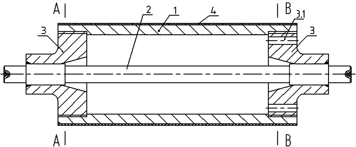
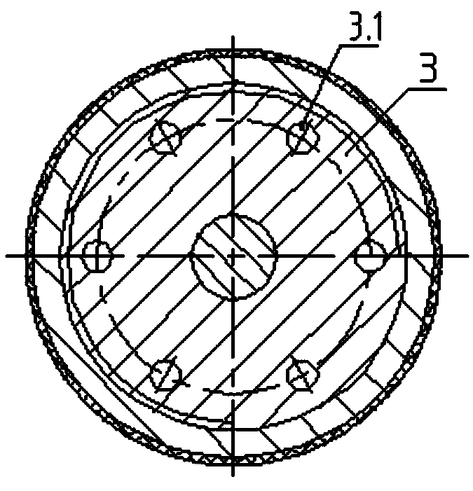
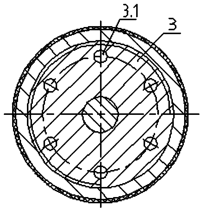
[0018] The high-temperature-resistant combined sinking roller shown in the attached figure includes a roller 1, a roller shaft 2, and two connecting bushes 3; the connecting bushing 3 is a stepped structure, and the big end is a flange; The outer circumference of the disc is provided with external threads, the spigot holes at both ends of the roller are internal thread holes, and the external threads on the outer circumference of the connecting sleeve 3 flange are connected with the spigot holes at both ends of the roller as internal thread holes.

[0019] The roller shaft 2 is an integral structure that axially penetrates the inner holes of the two connecting sleeves 3, and is fixedly connected with the two connecting sleeves; several (six in this embodiment) are evenly distributed on the flanges of the connecting sleeves 3 in the circu...


PUM


Abstract

The invention discloses a high-temperature-resistant combined type sinking roll which comprises a roller, a roll shaft and two connecting shaft sleeves; the connecting shaft sleeves are of stepped structures; flange plates are arranged at the large ends of the connecting shaft sleeves; spigot holes in the two ends of the roller sleeve and are fixedly connected with the flange plates of the connecting shaft sleeves; external threads are formed in the external circumferences of the flange plates of the connecting shaft sleeves; the spigot holes in the two ends of the roller are internal threadedholes; the external threads in the external circumferences of the flange plates of the connecting shaft sleeves are in internal threaded hole connection with the spigot holes in the two ends of the roller; the roll shaft is of an integral structure axially penetrating through inner holes of the two connecting shaft sleeves, and is fixedly connected with the two connecting shaft sleeves; axial through holes communicating with an inner cavity of the roller are uniformly and circumferentially formed in the flange plates of the connecting shaft sleeves; and the axial through holes in the flange plates of the connecting shaft sleeves at the two ends are formed in the circumferential direction of the center axis of the roller in a staggered manner. As a further improvement, the surface of the roller is coated with a metal ceramic coating. The high-temperature-resistant combined type sinking roll is high in structural strength and rigidity, in the application, when zinc liquid flows throughthe inner cavity of the roller, an eddy flow can be formed uniformly, and the high-temperature-resistant combined type sinking roll is high-temperature-resistant and wear-resistant.

Description

technical field [0001] The invention relates to the technical field of hot-dip galvanizing, in particular to a sinking roller on a hot-dip galvanizing device. Background technique [0002] The sinking roller on the existing hot-dip galvanizing device generally includes a roller, two roller shafts, and two connecting bushings. The connecting bushings have a stepped structure, and the big end is a flange. The connecting shaft sleeve flange is fixedly connected; the small end of the connecting shaft sleeve is set on one end of the roller shaft and fixedly connected. The main defects of this kind of sinking roller are: first, the structural strength and rigidity are poor; A swirl flow is formed when circulating in the inner cavity of the roller; the third is that the assembly or disassembly of the roller and the connecting sleeve is time-consuming and troublesome. Contents of the invention [0003] Aiming at the deficiencies of the prior art, the present invention provides a ...

Claims


Application Information

Patent Timeline
Patent Type & Authority Applications(China)
IPC IPC(8): C23C2/06
CPCC23C2/003C23C2/06
Inventor 孙颖
Owner 孙颖
Why Eureka
Try Eureka