Novel electronic locker lock

An electronic and storage technology, which is applied in the field of new electronic locker locks, can solve the problems of inconvenient installation, high power consumption of motors, and non-waterproof, etc., and achieve the effect of easy installation, stable structure, and high stability

Active Publication Date: 2018-07-10
XIAMEN MAKE LOCKS MFGR CO LTD
View PDF8 Cites 5 Cited by
  • Summary
  • Abstract
  • Description
  • Claims
  • Application Information

AI Technical Summary

Problems solved by technology

[0008] The purpose of the present invention is to provide a new type of electronic locker lock to solve the current problems of traditional elec

Method used


Image

  • Novel electronic locker lock
  • Novel electronic locker lock
  • Novel electronic locker lock

Examples


Embodiment Construction

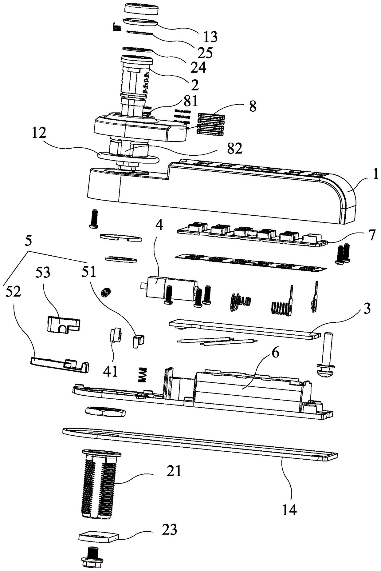
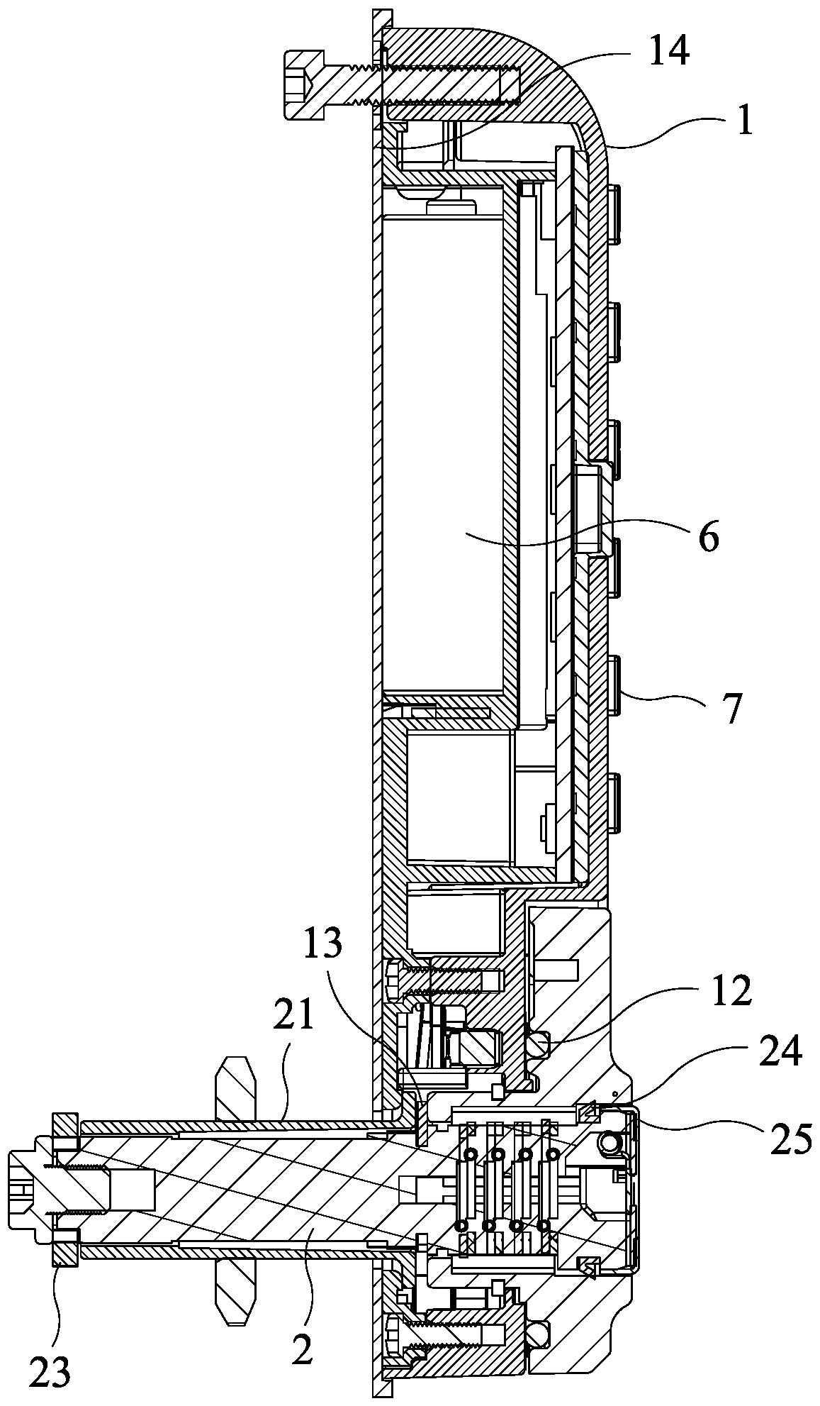
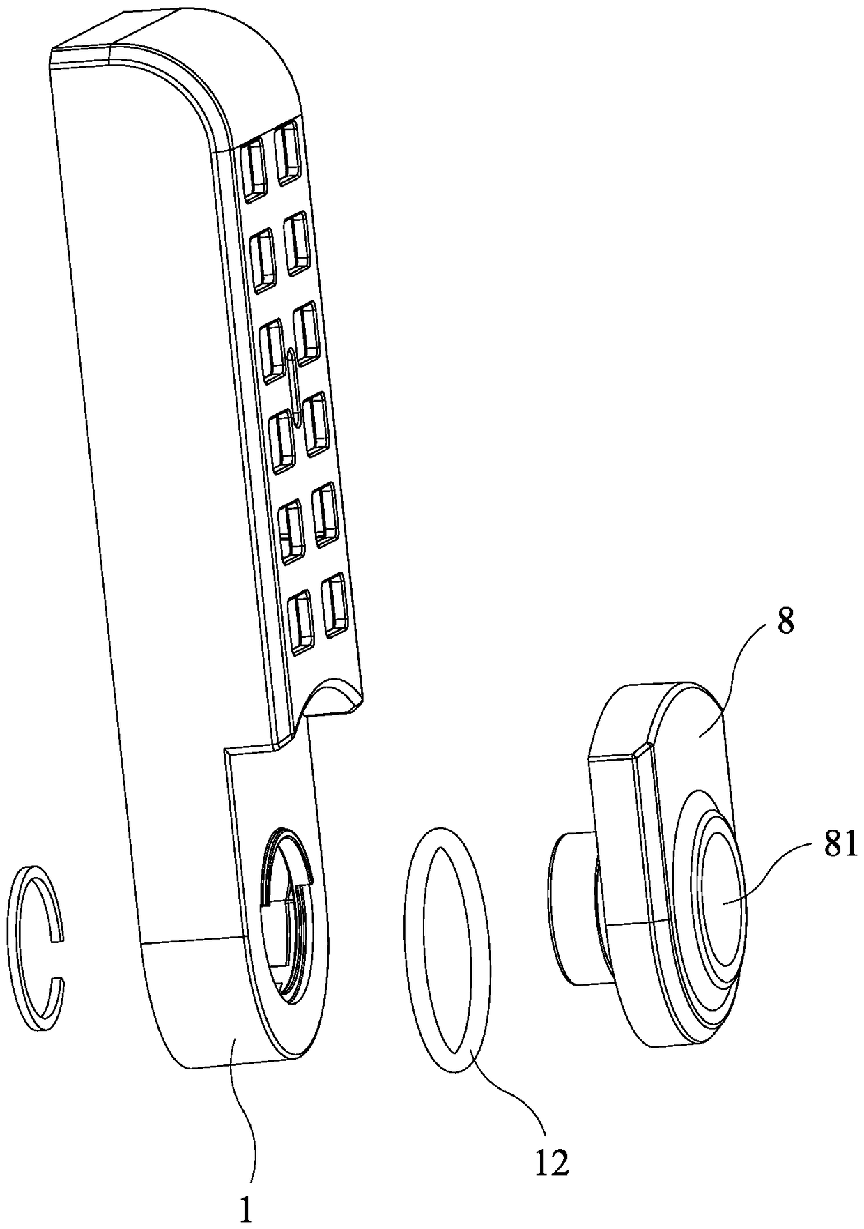
[0046] Such as Figure 1 to Figure 15 As shown, a novel electronic locker lock disclosed by the present invention includes a lock casing 21 , a lock cylinder 2 , a circuit board 3 , a motor assembly 4 , a clutch mechanism 5 and a battery assembly 6 installed in the casing 1 . The button assembly 7 is installed on the outside of the shell 1, the button assembly 7, the motor assembly 4, the battery assembly 6 are electrically connected to the circuit board 3, and the battery assembly 6 supplies power to the motor assembly 4 and the circuit board 3. When the password input is correct, the button assembly 7 transmits the information to the circuit board 3, and the circuit board 3 controls the motor assembly 4 to work. A cam 41 is installed on the output shaft of the motor assembly 4 . A handle 8 is also installed on the outside of the shell 1, and the lock core 2 is installed in the lock housing 21. One end of the lock core 2 having a lock hole 22 is fixed in the shaft hole 81 of...


PUM


Abstract

The invention discloses a novel electronic locker lock. A lock shell, a lock cylinder, a circuit board, a motor assembly, an engagement and disengagement mechanism and a battery assembly are mounted in a shell. A button assembly is mounted on the outer side of the shell. The button assembly, the motor assembly and the battery assembly are electrically connected with the circuit board. A cam is mounted on an output shaft of the motor assembly. A grab handle is mounted on the outer side of the shell. The lock cylinder is mounted in the lock shell. The end, with a lock hole, of the lock cylinderis fixed in a shaft hole of the grab handle. The lock hole is exposed out of the outer side of the grab handle. A spring bolt mounted on the lock cylinder is exposed out of the inner side of the shell. The engagement and disengagement mechanism is located between the cam and the grab handle and adopts mechanical engagement and disengagement. When input passwords are correct, the button assembly transmits information to the circuit board, the circuit board controls the motor assembly to work, when the cam is driven to rotate, the engagement and disengagement mechanism is controlled by the cam to be in a disengagement state or an engagement state, the grab handle can be rotated to drive the lock cylinder to rotate, and the spring bolt rotates for unlocking. The novel electronic locker lock is high in safety, is provided with an emergency key and is waterproof, low in power consumption and convenient to mount.

Description

technical field [0001] The invention relates to a novel electronic locker lock. Background technique [0002] With the improvement of the economic level, electronic smart lockers are widely used in homes, hotels, enterprises, public places and other places. Electronic smart cabinet locks are used more and more in people's lives, and more and more consumers pay more attention to the stability of product appearance and performance while pursuing product practicability. [0003] The clutch structure of traditional electronic locks mostly adopts an electromagnet structure; this structure has low security and is easily cracked by people using magnetic objects such as magnets. [0004] Most of the traditional electronic locks do not have an emergency key. When the electronics fails or the battery is completely dead, the cabinet door can only be opened by picking the lock or destroying the lock. [0005] Most of the traditional electronic locks are not designed to be waterproof, ...

Claims


Application Information

Patent Timeline
IPC IPC(8): E05B65/02E05B65/52E05B49/00E05B47/00E05B17/00E05B19/00
CPCE05B17/002E05B47/0001E05B47/0012E05B49/00E05B49/002E05B65/02E05B65/52E05B2047/0058E05B47/0615E05B47/0634E05B65/025
Inventor 赖宏亮
Owner XIAMEN MAKE LOCKS MFGR CO LTD
Why Eureka
Try Eureka