Supercharge Your Innovation With Domain-Expert AI Agents!

A flow control nozzle

A technology of flow control and nozzle, which is applied in the field of nozzle with high-precision adjustment of gas flow, can solve the problems of limiting the accuracy of flow adjustment, and achieve the effect of compact nozzle structure, easy repair and maintenance

Active Publication Date: 2019-10-18
CHINA ACAD OF AEROSPACE AERODYNAMICS
View PDF8 Cites 0 Cited by
  • Summary
  • Abstract
  • Description
  • Claims
  • Application Information

AI Technical Summary

Problems solved by technology

The third method is to use a combination of a regulating valve and a throttling device to adjust the gas flow. The commonly used throttling device is an orifice plate, which uses the sonic flow formed at the opening of the orifice plate to throttle the flow to prevent the influence of downstream pressure fluctuations. The gas pressure is adjusted by the regulating valve to stabilize the gas flow to a certain level. The advantage of this method is that the influence of the downstream flow of the orifice plate on the upstream is stabilized to a certain extent, and a relatively stable downstream flow field is provided. The disadvantage is that the flow fluctuation at the throat of the orifice plate is limited. flow regulation accuracy

Method used


Image

  • A flow control nozzle
  • A flow control nozzle
  • A flow control nozzle

Examples


Embodiment Construction

[0021] The present invention will be described in further detail below in conjunction with the accompanying drawings and specific embodiments.

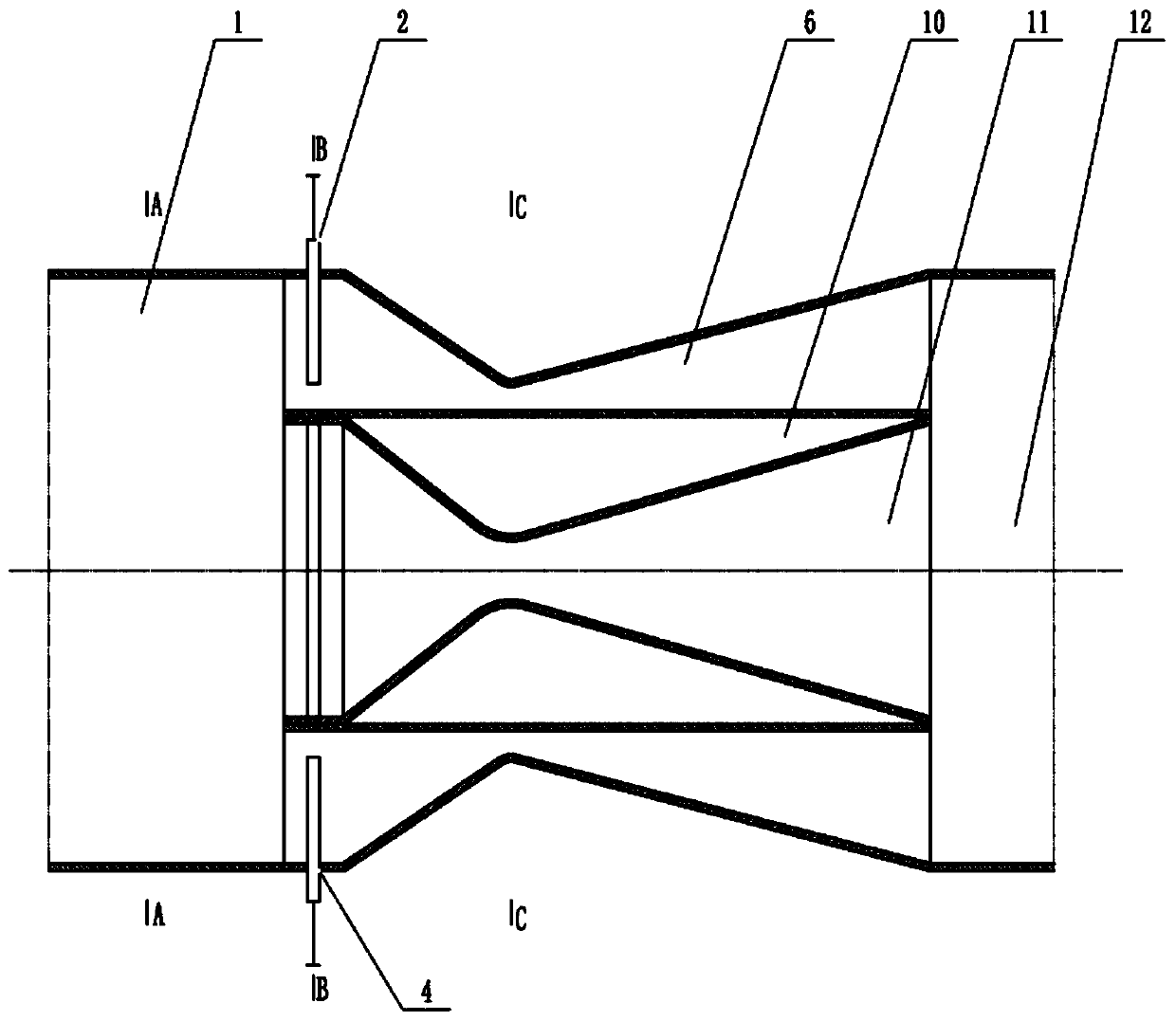
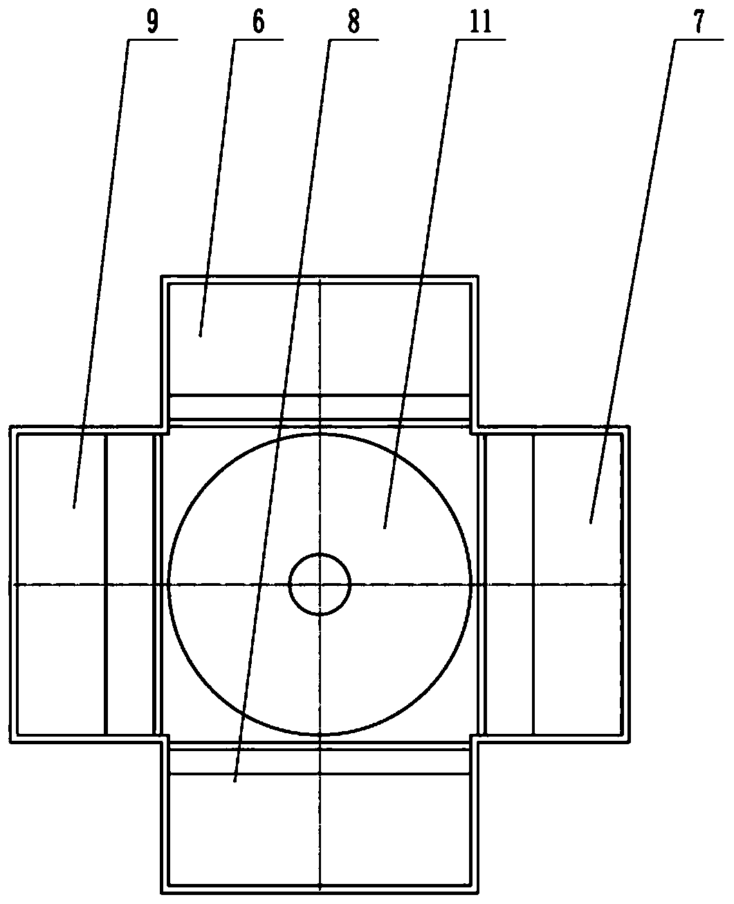
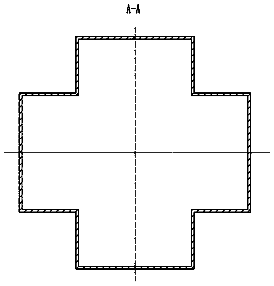
[0022] Such as figure 1 As shown, the structure diagram of the gas flow control nozzle, the nozzle includes a pressure stabilizing section 1, an upper flapper valve 2, a right flapper valve 3, a lower flapper valve 4, a left flapper valve 5, and an upper binary nozzle 6 , right binary nozzle 7, lower binary nozzle 8, left binary nozzle 9, nozzle structure block 10, center ternary nozzle 11, diffusion section 12; wherein the main function of voltage stabilizing section 1 is to reduce The flow velocity of the gas at the inlet of the nozzle improves the stability of the air flow and reduces the degree of turbulence. The front end connection of the gate valve 5 gradually transitions into a special-shaped structure, such as figure 2 shown. The upper flapper valve 2, the right flapper valve 3, the lower flapper valve 4, and the left fla...


PUM


Abstract

The invention discloses a flow control jet pipe which comprises a pressure stabilizing segment, a jet pipe combination unit, an insert plate unit and a diffusion segment. The jet pipe combination unitcomprises a ternary jet pipe in the center and a binary jet pipe combined to the sidewall of the ternary jet pipe, the insert plate unit is installed in an inlet of the jet pipe combination unit andcomprises a single insert plate which can shield the inlet of the binary jet pipe and double insert plates which can shield both the inlet of the binary jet pipe and the inlet of the ternary jet pipe,the pressure stabilizing segment includes a cylinder whose shape is the same with that of the inlet of the jet pipe combination unit, and the diffusion segment includes a cylinder whose shape is thesame with that of the outlet of the jet pipe combination unit. The flow control jet pipe can be used to solve the problem that gas flow control is large is span and hard to control accurately, is compact in structure and easy to maintain, and uses block design and combined control.

Description

technical field [0001] The invention relates to a supersonic nozzle, in particular to a nozzle used for high-precision regulation of gas flow. Background technique [0002] At present, the development of nuclear power equipment requires gas-entrained liquid tests. The gas flow span of different test conditions is large. With the deepening of research, the test accuracy requirements gradually increase. Due to the existence of gas-liquid two-phase flow during the test process, liquid ups and downs, gas sound waves The reverse propagation phenomenon causes the gas pressure and flow to be unstable, which makes the accuracy of the gas entrainment test not high. In order to improve the accuracy of the gas entrainment test, it is necessary to provide a high-precision gas flow adjustment system. [0003] The first method of gas flow regulation is to use the flowmeter feedback signal to the regulating valve, the regulating valve responds and adjusts the opening and position, and then...

Claims


Application Information

Patent Timeline
Patent Type & Authority Patents(China)
IPC IPC(8): G01M10/00
Inventor 张建伟晏硕赵小运
Owner CHINA ACAD OF AEROSPACE AERODYNAMICS
Features
  • R&D
  • Intellectual Property
  • Life Sciences
  • Materials
  • Tech Scout
  • Unparalleled Data Quality
  • Higher Quality Content
  • 60% Fewer Hallucinations
Learn More