Consumable chip and consumable container

A technology of consumable chips and consumable containers, which is applied in the fields of instruments, electrography, optics, etc., can solve the problems of modulation signal error, affecting the improvement of the sensitivity of radio frequency consumable chips, etc., and achieve stability, good compatibility and high sensitivity Effect

Active Publication Date: 2018-07-10
ZHUHAI TIANWEI TECH DEV CO LTD
View PDF7 Cites 7 Cited by
  • Summary
  • Abstract
  • Description
  • Claims
  • Application Information

AI Technical Summary

Problems solved by technology

If the parasitic power supply circuit 10 overcompensates, it will cause the modulation signal obtained by the demodulation circuit 20 to be wrong, and when the sensitivity of the modulation circuit is very high, this effect cannot be ignored, which seriously affects the improvement of the sensitivity of the radio frequency consumable chip

Method used


Image

  • Consumable chip and consumable container
  • Consumable chip and consumable container
  • Consumable chip and consumable container

Examples


no. 1 example

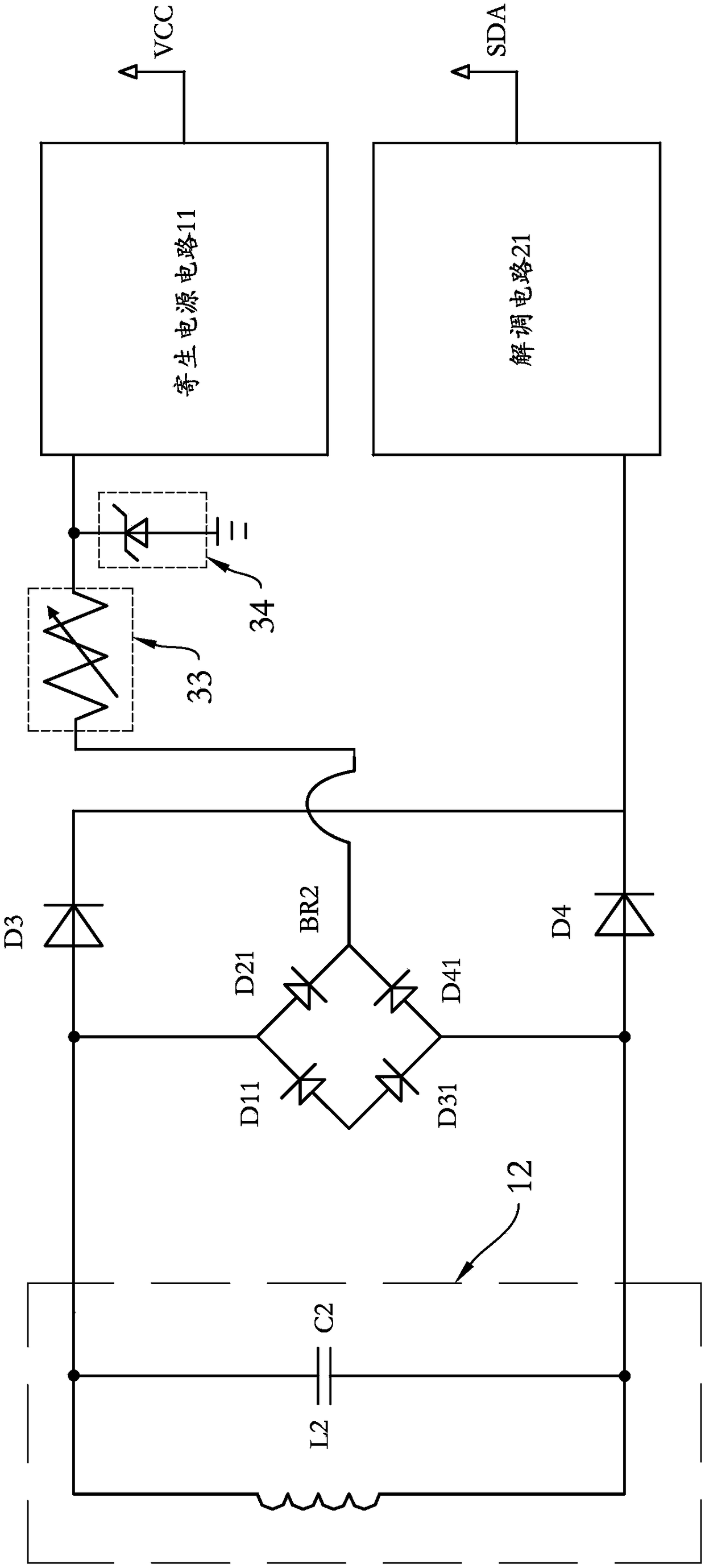
[0036] see image 3 , image 3 It is the electrical schematic diagram of the first embodiment of the chip of the present invention. In this embodiment, the signal exchanging circuit includes a coil for receiving the radio frequency signal sent by the laser printer, and can obtain energy from the radio frequency signal to form resonance and generate a carrier signal with a certain oscillation frequency. The signal exchange circuit also includes a parallel inductor L2 and capacitor C2, and a bridge circuit BR2, which is composed of image 3 It can be seen that in this embodiment, the diodes D11, D21, D31, and D41 form a bridge circuit BR2, and the radio frequency signal can be rectified by the bridge circuit BR2, and a stable voltage can be obtained by the voltage stabilizing circuit 30 and input to the parasitic power supply circuit 11.

[0037] In this embodiment, the diodes D11, D21, D31, and D41 form a bridge circuit BR2, and the radio frequency signal transmitted by the s...

no. 2 example

[0048] see Figure 6 , Figure 6 It is the electrical schematic diagram of the second embodiment of the chip of the present invention. In this embodiment, the signal exchanging circuit includes a coil, which can receive the radio frequency signal sent by the laser printer, and can obtain energy from the radio frequency signal to form resonance. The signal exchange circuit includes an inductance L3, a capacitor C3 and a bridge circuit BR3, by Figure 6 It can be seen from the figure that the diodes D12, D22, D32, and D42 in this embodiment form a bridge circuit BR3, and the radio frequency signal can be rectified by the bridge circuit BR3, and the stable voltage obtained by the voltage stabilizing circuit 50 is input to the parasitic power supply circuit 12.

[0049] In this embodiment, the diodes D12, D22, D32, and D42 form a bridge circuit BR3, and the radio frequency signal transmitted by the signal exchange circuit can be rectified by the bridge circuit BR3, and after bei...


PUM


Abstract

The invention provides a consumable chip and a consumable container; a signal exchange circuit to carry out signal exchanging with the outside is arranged on a consumable chip substrate; a parasitic power circuit of electricity is acquired from the signal exchange circuit; a signal decoding circuit is decoded from the signal exchange circuit; the consumable chip also comprises a voltage stabilizing circuit between the signal exchange circuit and the parasitic power circuit; the voltage stabilizing circuit is provided with a voltage stabilizing diode; voltage pre-stabilizing is performed by making use of the characteristic that before inverse voltage of the voltage stabilizing diode is not broken down, voltages of the two ends of the voltage stabilizing diode are kept unchanged. The invention also provides a consumable container with the consumable chip. The consumable chip provided herein can effectively avoid influence upon input voltage of the parasitic power circuit during signal modulation, so that the sensitivity of the demodulating circuit is higher.

Description

technical field [0001] The invention relates to the field of printing consumables, in particular to a consumable container used in a printer and a consumable chip used in the consumable container. Background technique [0002] Toner cartridge is a common laser printing consumable, widely used in laser printers. Most of the existing toner cartridges are provided with a chip, and the chip usually stores information such as the model of the toner cartridge, the model of the applicable laser printer, and the remaining amount of toner in the toner cartridge. Whenever the toner cartridge is installed on the laser printer, the laser printer will read the above information from the chip to determine whether the toner cartridge is suitable for the laser printer. [0003] The chip of some existing toner cartridges is a non-contact chip, that is, the communication between the chip and the laser printer is realized through radio frequency technology (RFID). The circuit block diagram o...

Claims


Application Information

Patent Timeline
Patent Type & Authority Applications(China)
IPC IPC(8): G03G15/08
CPCG03G15/08G03G15/0863
Inventor 徐建强谢立功文冠果
Owner ZHUHAI TIANWEI TECH DEV CO LTD
Why Eureka
Try Eureka