Design method of amplifying circuit and amplifying circuit

A technique for amplifying circuits and design methods, applied in CAD circuit design, calculation, electrical digital data processing, etc., can solve problems such as system instability and achieve the effect of gain increase

Active Publication Date: 2018-07-10
杨娇丽
View PDF10 Cites 2 Cited by
  • Summary
  • Abstract
  • Description
  • Claims
  • Application Information

AI Technical Summary

Problems solved by technology

[0002] In the design of the amplifier circuit, in order to make the whole system more stable, a negative feedback structure is generally introduced to carry out negative feedback on the amplifier device, but this is at the expense of the gain of the amplifier module; for example, due to the introduction of negative feedback, the amplifier module The gain is less than the gain of the amplifying device itself
[0003] Conversely, although the positive feedback structure can increase the gain of the amplifier module, the current design will try to avoid introducing positive feedback, because it will bring many negative problems to the system, typically leading to system instability.

Method used


Image

  • Design method of amplifying circuit and amplifying circuit
  • Design method of amplifying circuit and amplifying circuit
  • Design method of amplifying circuit and amplifying circuit

Examples


Embodiment Construction

[0032] The present invention will be further described in detail below through specific embodiments in conjunction with the accompanying drawings. Wherein, similar elements in different implementations adopt associated similar element numbers. In the following implementation manners, many details are described for better understanding of the present application. However, those skilled in the art can readily recognize that some of the features can be omitted in different situations, or can be replaced by other elements, materials, and methods. In some cases, some operations related to the application are not shown or described in the description, this is to avoid the core part of the application being overwhelmed by too many descriptions, and for those skilled in the art, it is necessary to describe these operations in detail Relevant operations are not necessary, and they can fully understand the relevant operations according to the description in the specification and genera...


PUM


Abstract

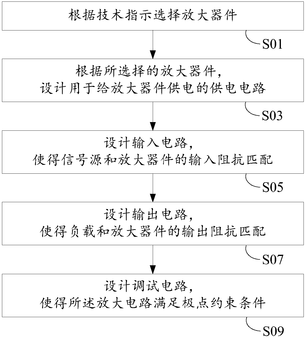
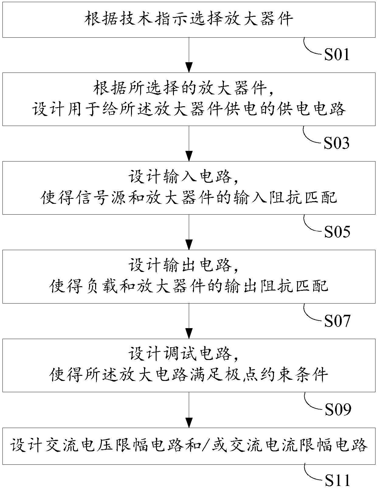
The invention discloses a design method of an amplifying circuit and the amplifying circuit. The design method comprises the steps that an amplifying device is selected according to a technical instruction; according to the selected amplifying device, a power supply circuit used for supplying power to the amplifying device is designed; an input circuit is designed, so that a signal source and theamplifying device are matched in input impedance; an output circuit is designed, so that a load and the amplifying device are matched in output impedance; and a debugging circuit is designed, so thatthe amplifying circuit meets a pole constraint condition, wherein the pole constraint condition comprises that at least one pole of the amplifying circuit in a complex plane moves from an initial position to a right half plane, a virtual axis or a position nearby the virtual axis at least along with increase of input signal power and is finally stabilized at the virtual axis, the right half planeor a left half plane. Compared with the prior art, the gain of the amplifying circuit is increased.

Description

technical field [0001] The invention relates to the field of amplifier circuits, in particular to an amplifier circuit design method and the amplifier circuit. Background technique [0002] In the design of the amplifier circuit, in order to make the whole system more stable, a negative feedback structure is generally introduced to carry out negative feedback on the amplifier device, but this is at the expense of the gain of the amplifier module; for example, due to the introduction of negative feedback, the amplifier module The gain is less than the gain of the amplifier itself. [0003] Conversely, although the positive feedback structure can increase the gain of the amplifier module, the current design will try to avoid introducing positive feedback, because it will bring many negative problems to the system, typically leading to system instability. Contents of the invention [0004] Considering the above situation, the present application provides a method for designi...

Claims


Application Information

Patent Timeline
Patent Type & Authority Applications(China)
IPC IPC(8): G06F17/50
CPCG06F30/36G06F2111/04
Inventor 杨娇丽
Owner 杨娇丽
Why Eureka
Try Eureka