Photovoltaic component laminating technology

A technology for photovoltaic modules and lamination processes, applied in lamination, photovoltaic power generation, lamination devices, etc., can solve the problems of high input cost and inapplicability, and achieve the effect of improving product yield

Active Publication Date: 2018-07-10
CSI SOLAR POWER GROUP CO LTD +1
View PDF6 Cites 12 Cited by
  • Summary
  • Abstract
  • Description
  • Claims
  • Application Information

AI Technical Summary

Problems solved by technology

However, the above methods all need to replace or modify the machine, and the in

Method used


Image

  • Photovoltaic component laminating technology
  • Photovoltaic component laminating technology
  • Photovoltaic component laminating technology

Examples


Embodiment Construction

[0029] In order to make the object, technical solution and advantages of the present invention clearer, the present invention will be described in detail below in conjunction with the accompanying drawings and specific embodiments.

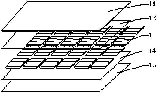
[0030] see figure 1 Shown is a structural schematic diagram of the photovoltaic module in the photovoltaic module lamination process of the present invention. The photovoltaic module includes a glass plate 11, a TPT (not shown), an encapsulation film 12, a solar cell string 1, an encapsulation film 14, a TPT (not shown) and a glass plate 15 stacked sequentially from top to bottom. .

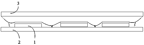
[0031] Such as figure 2 Shown is a conventional heating method for the lamination process of photovoltaic modules. In the traditional heating method, the laminator only has the heating plate 2 located below the photovoltaic module, and the photovoltaic module is heated mainly through the contact heat conduction of the heating plate 2 . The photovoltaic module is...


PUM


Abstract

The invention provides a photovoltaic component laminating technology. The technology comprises the following steps of (1) providing a photovoltaic component and a laminated machine used for laminating the photovoltaic component, wherein the laminated machine is provided with a heating plate, and a spontaneous heating plate is arranged above the photovoltaic component; (2) setting a laminated parameter on the laminated machine, wherein the temperatures of the heating plate and the spontaneous heating plate reach an assigned temperature, the photovoltaic component is put into the laminated machine and a lid is closed; (3) carrying out vacuum-pumping operation among each layer of the photovoltaic component; (4) pressurizing the upper chamber of the laminated machine and pressing the spontaneous heating plate to the top of the photovoltaic component, wherein the spontaneous heating plate and the heating plate simultaneously heat the photovoltaic component; and (5) after lamination, inflating the lower chamber of the laminated machine, carrying out vacuum pumping on the upper chamber, opening an upper lid, taking out the photovoltaic component and completing the lamination. The temperatures of the heated photovoltaic component at different phases are effectively controlled, photovoltaic component lamination time is shortened and production efficiency is increased.

Description

technical field [0001] The invention relates to the technical field of solar photovoltaic modules, in particular to a photovoltaic module lamination process that shortens the lamination time of photovoltaic modules and improves the lamination efficiency of photovoltaic modules. Background technique [0002] The lamination process of photovoltaic modules is an important part of the photovoltaic module manufacturing process. In the laminator, the air in the photovoltaic module is drawn out by vacuuming, and then heated to melt the encapsulation film to bond the solar cell strings, glass and backplane glass together. The main structure of the laminator is composed of upper and lower vacuum chambers, silica gel plates, heating systems, vacuum systems, heating control systems, control systems, etc. [0003] The lamination process adopted in the lamination process is to complete the exhaustion, heating, and curing in the lamination machine at one time. In the traditional photovo...

Claims


Application Information

Patent Timeline
IPC IPC(8): H01L31/18H01L31/048B32B37/06B32B37/10B32B38/18
CPCH01L31/048H01L31/1876B32B37/06B32B37/10B32B38/1858Y02E10/50Y02P70/50
Inventor 范喜燕张磊杨峰
Owner CSI SOLAR POWER GROUP CO LTD
Why Eureka
Try Eureka