Scanning bed and medical imaging equipment with the same

A scanning bed and bed board technology is applied in the field of scanning beds and medical imaging equipment having the scanning bed, which can solve the problems of multiple transmission levels, influence on system imaging quality, influence of magnetic field uniformity gradient field linearity, etc., so as to improve transmission accuracy Effect

Active Publication Date: 2022-02-11
SHANGHAI NEUSOFT MEDICAL TECH LTD
View PDF12 Cites 0 Cited by
  • Summary
  • Abstract
  • Description
  • Claims
  • Application Information

AI Technical Summary

Problems solved by technology

[0011] In the first driving mode, the first-stage transmission adopts the rack and pinion transmission mode. Due to the limitation of this transmission mode, the driving motor must be arranged at a position very close to the magnet, and the motor and the shielding cover protecting the motor are both made of iron. Magnetic parts will have a relatively large impact on the uniformity of the magnetic field and the linearity of the gradient field, thereby affecting the imaging quality of the system
[0012] In the second driving mode, it includes three-stage transmission, and its transmission levels are many, so that the transmission accuracy is poor

Method used


Image

  • Scanning bed and medical imaging equipment with the same
  • Scanning bed and medical imaging equipment with the same
  • Scanning bed and medical imaging equipment with the same

Examples


Embodiment Construction

[0041] The present invention will be described in detail below in conjunction with the accompanying drawings, so that those skilled in the art can accurately understand the technical solution of the present invention.

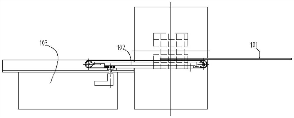
[0042] The up, down, left and right directions described in this article refer to the normal use status of the medical imaging equipment. When the medical imaging equipment is in use, the direction perpendicular to the ground is the up and down direction, the direction pointing vertically to the ground is the down direction, and it is vertically away from the ground. The direction of the upward direction; with the length direction of the scanning bed as the front and rear direction, in the length direction of the scanning bed, the direction towards the imaging equipment of the medical imaging equipment is the front, and the direction away from the imaging equipment is the rear, or in other words, the scanning bed is from the rear It can be sent into the imaging ...


PUM


Abstract

The invention provides a scanning bed and medical imaging equipment with the scanning bed. The motor can be arranged at a position away from the magnet, thereby preventing the motor from affecting the uniformity of the magnetic field and the linearity of the gradient field. At the same time, an annular belt and an opening are used With matching two-stage transmission, the transmission precision is improved. The scanning bed of the present invention includes a support device, a driving source, a bed board, a middle board, an opening belt and an endless belt, the middle board is fixedly connected with the opening belt, the bed board is fixedly connected with the endless belt, and the front end of the opening belt is provided with a first connecting device connected with the driving source. a driving wheel, so that under the driving of the first driving wheel, the middle plate is driven to move back and forth relative to the supporting device, and the driving source is arranged at the rear end; the annular belt is sleeved on the middle plate, and is connected with the first connecting piece fixed with the supporting device, In order to move synchronously when the middle board moves back and forth relative to the supporting device, and then drive the bed board to move back and forth in the same direction relative to the middle board.

Description

technical field [0001] The invention relates to the technical field of medical imaging equipment, in particular to a scanning bed and medical imaging equipment with the scanning bed. Background technique [0002] Existing medical imaging devices all have a scanning bed for carrying the examinee. The scanning bed used for the medical imaging device will be described below by taking the magnetic resonance imaging system as an example. [0003] Magnetic Resonance Imaging (MRI, Magnetic Resonance Imaging) is widely used in clinical medicine and scientific research, and it mainly includes magnets, gradient coils, radio frequency transmitting coils, radio frequency receiving coils and a scanning table carrying the object to be examined. The scanning bed is used to move the inspected object to the main magnet and gradient field generated by the magnet and gradient coils. The radio frequency transmitting coil excites the inspected object to generate magnetic resonance signals, and t...

Claims


Application Information

Patent Timeline
Patent Type & Authority Patents(China)
IPC IPC(8): A61B5/055
CPCA61B5/055A61B6/0471A61B6/0407A61B5/704A61G13/02A61G2210/50
Inventor 侯贵堂石峰
Owner SHANGHAI NEUSOFT MEDICAL TECH LTD
Why Eureka
Try Eureka