Sickbed convenient for patient transfer

A technology for sickbeds and patients, which is applied in the field of sickbeds that are convenient for patients to transfer. It can solve the problems of manual lifting, difficulty in lifting, etc., and achieve the effects of preventing patients from falling, saving treatment time, and reducing manual labor.

Inactive Publication Date: 2018-07-13
ZHENGZHOU AIBOER MEDICAL EQUIP
View PDF16 Cites 14 Cited by
  • Summary
  • Abstract
  • Description
  • Claims
  • Application Information

AI Technical Summary

Problems solved by technology

[0003] The purpose of the present invention is: in order to solve the problem of manual lifting when patients are transferred, and

Method used


Image

  • Sickbed convenient for patient transfer
  • Sickbed convenient for patient transfer

Examples


Embodiment 1

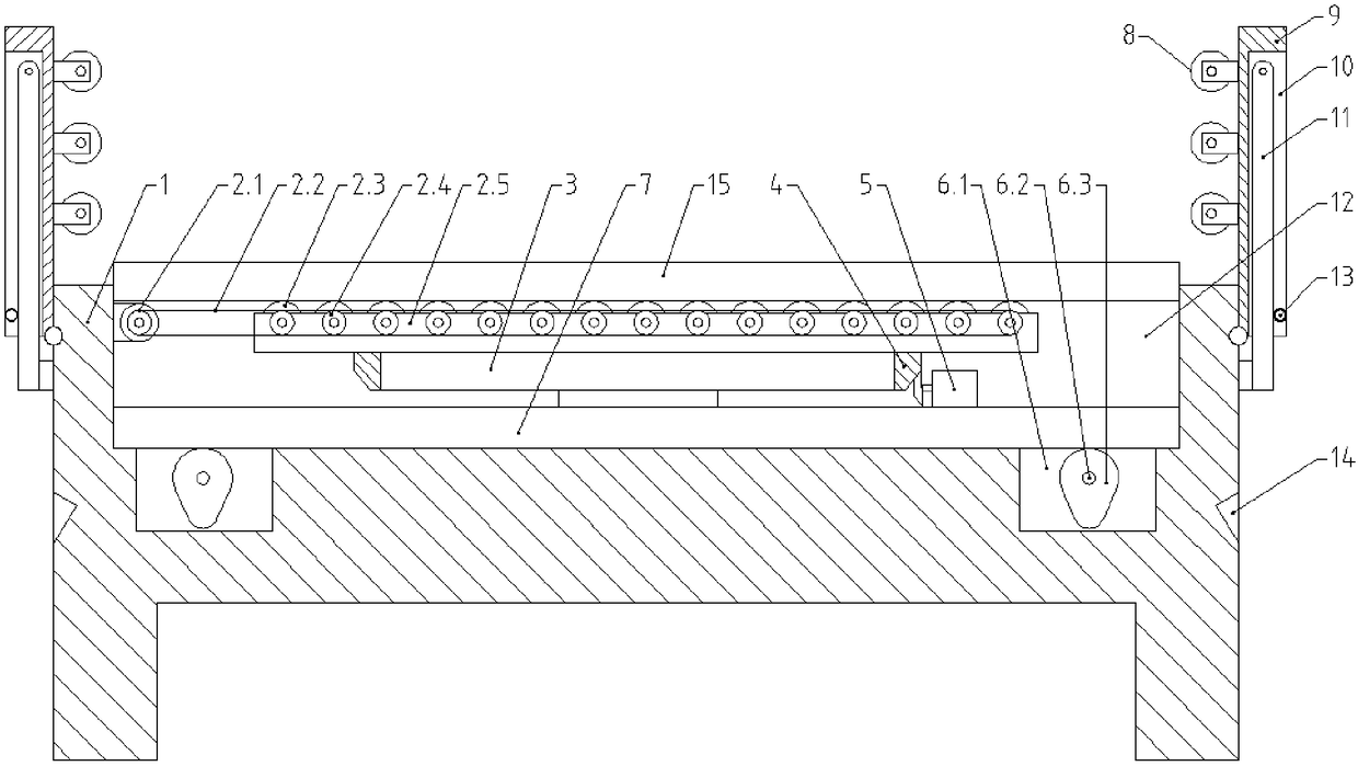
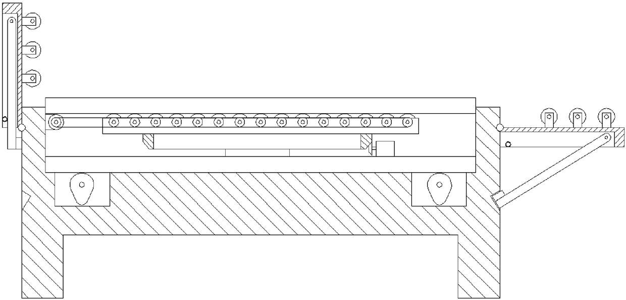
[0019] A hospital bed that is convenient for patients to transfer, comprising a bed body 1 and a bed board 15, a groove 12 for accommodating the bed board 15 is opened in the center of the bed body 1, installation grooves 10 are arranged at the bottom of both sides of the groove 12, and a lifting device is arranged in the installation groove 10. Device 6, a lifting plate 7 is arranged above the lifting device 6, the lower surface of the lifting plate 7 is in contact with the lifting devices 6 on both sides, the bed plate 15 is arranged above the lifting plate 7, and the lifting plate 7 is provided with a roller mechanism 2 that drives the bed plate 15 to move , the roller mechanism 2 includes a roller frame 2.5 arranged on the lifting plate 7, a number of rollers 2.3 are arranged on the roller frame 2.5, a gear 2.4 is arranged at one end of the roller 2.3, and an output shaft with a gear 2.4 is arranged on the groove wall on one side of the groove 12. Motor 2.1, the gear 2.4 on...

Embodiment 2

[0022] This embodiment improves on the basis of Embodiment 1:

[0023] Lifting device 6 comprises the rotating shaft 6.2 that is arranged in groove 12, and rotating shaft 6.2 is sleeved with some cams 6.3, and rotating shaft 6.2 one end is connected with lifting motor, and the rotation direction of rotating shaft 6.2 in both sides lifting device 6 is opposite.

[0024] The advantages of the above improvements are: the cam lifting mechanism is simple in structure, stable in function, and fully meets the lifting requirements. At the same time, the rotation directions of the rotating shafts in the lifting devices on both sides are opposite, so that when the cams on both sides rotate, the forces on the lifting plate cancel each other, so that the lifting plate can be lifted. rise steadily.

Embodiment 3

[0026] This embodiment improves on the basis of Embodiment 1:

[0027] The lifting plate 7 is provided with a circular rotating platform 3, the roller frame 2.5 is arranged on the rotating platform 3, the outer bevel gear ring 4 is arranged on the circumference of the rotating platform 3, and the belt that cooperates with the outer bevel ring is arranged on one side of the lifting plate 7. The bevel gear 2.4 rotates the motor 5.

[0028] The advantages of the above improvements are: the rotating platform can rotate the roller mechanism to different directions, so that the bed board can be transferred in different directions, so as to fully adapt to different placement positions of the hospital bed, and ensure the normal use of the function of the hospital bed for transferring patients.


PUM


Abstract

The invention discloses a sickbed convenient for patient transfer, relates to the technical field of sickroom nursing equipment and solves the problem that it is troublesome to lift by using manpowerand difficult to lift for heavier patients when transferring patient. The sickbed includes a bed body and a bed board. The center of the bed body is provided with a groove for accommodating the bed board. Mounting grooves are arranged at the bottoms of both sides of the groove. A lifting device is arranged in the mounting groove. A lifting plate is arranged above the lifting device. The lower surface of the lifting plate is in contact with the lifting devices at the two sides. The bed board is arranged above the lifting plate. The lifting flat plate is provided with a roller mechanism for driving the bed board to move. The roller mechanism includes a roller frame arranged on the lifting flat plate. A plurality of rollers are arranged on the roller frame. A gear is arranged at one end of the roller. A motor with an output shaft arranged with a gear is arranged on the groove wall of one side of the groove. Gears on a plurality of rollers are matched with the motor through gear belts.

Description

technical field [0001] The invention relates to the technical field of nursing equipment in wards, and more particularly relates to a hospital bed which is convenient for patients to transfer. Background technique [0002] The hospital bed is the most commonly used nursing equipment in the hospital. It is used for the patient to sit and rest. Some patients who cannot move by themselves need to be transferred by mobile devices when they need to undergo surgery or other examinations. However, the existing general hospital beds do not have the function of assisting patients in transferring, so manual transfer is usually used when transferring patients. Lifting the patient to prevent transfer to the mobile device is not only cumbersome, but also very difficult to lift the patient for heavy patients. Contents of the invention [0003] The purpose of the present invention is: in order to solve the problem of manually lifting the patient when transferring, and for the heavy pati...

Claims


Application Information

Patent Timeline
IPC IPC(8): A61G7/00A61G7/05A61G7/10
CPCA61G7/00A61G7/0507A61G7/1034
Inventor 曹清太
Owner ZHENGZHOU AIBOER MEDICAL EQUIP
Why Eureka
Try Eureka