Cooking fume purification device

A technology of oil fume purification and installation seat, which is applied in the direction of oil fume removal, chemical instruments and methods, household heating, etc., which can solve problems such as difficult cleaning, large changes in purification efficiency, and poor smoke exhaust, so as to avoid polluting the air and improve purification Effect, the effect of structural design innovation

Inactive Publication Date: 2018-07-13
CHENGDU PUJIANG KEXIAN TECH
View PDF0 Cites 1 Cited by
  • Summary
  • Abstract
  • Description
  • Claims
  • Application Information

AI Technical Summary

Problems solved by technology

[0002] At present, there are several purification methods for oil fume purification devices, such as electrostatic method, wet method, and dry method. Excessive deposits on the electrode surface of electrostatic oil fume purifiers will easily lead to a sharp decrease in purification efficiency, and it is difficult to clean, which is not conducive to the long-term operation of the equipment; its circuit The circuit board is the core technology of various manufacturers, and it has low versatility, and the cost of replacing the circuit board is high. Wet fume purifiers, such as water fume hoods, chemical absorption, etc., have large resistance, high price, large water consumption, and dehydration is not easy. Clean, it will cause great harm to the rear fan. At the same time, due to the large resistance, it is also not conducive to the selection of the fan. The dry oil fume purifier is large in size and the purification efficiency changes greatly. The filter and adsorption materials must be replaced regularly. Replacing the adsorbed material in time will cause poor smoke exhaust and bring inconvenience to the operation. At the same time, because of its large size, it cannot be used in restaurants and restaurants without large installation sites. The customer is even more unsatisfied, and at the same time, the direct discharge of the cleaned sewage of the device is a waste of water resources, so a kind of oil fume purification device is proposed

Method used


Image

  • Cooking fume purification device
  • Cooking fume purification device
  • Cooking fume purification device

Examples


Embodiment Construction

[0016] The following will clearly and completely describe the technical solutions in the embodiments of the present invention with reference to the accompanying drawings in the embodiments of the present invention. Obviously, the described embodiments are only some, not all, embodiments of the present invention. Based on the embodiments of the present invention, all other embodiments obtained by persons of ordinary skill in the art without making creative efforts belong to the protection scope of the present invention.

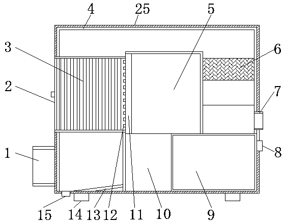
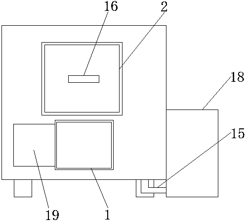
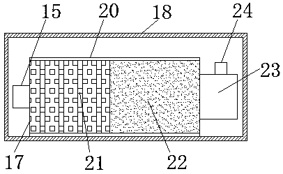
[0017] see Figure 1~3 , in the embodiment of the present invention, the oil fume purification device includes a smoking port 1, a mounting base 2, an electrostatic layer 3, an exhaust pipe 4, a support column 5, a packing layer 6, an exhaust port 7, a water injection port 8, a water tank 9, a A water pump 10, a water spray pipe 11, a nozzle 12, an inclined plate 13, a pad 14, a drain pipe 15, a handle 16, a filter device 17, a filter box 18, a smoking machine...


PUM


Abstract

The invention discloses a cooking fume purification device which comprises a fume sucking hole, a mounting base, an electrostatic layer, an exhaust pipeline, a support column, a packing layer, an exhaust hole, a water injection hole, a water tank, a first water pump, a water ejection tube, a nozzle, an inclined plate, cushion blocks, a water discharge tube, a handle, a filtering device, a filtering tank, a fume sucking machine, a treatment tube, a primary filtering layer, a secondary filtering layer, a second water pump, a connecting tube and an outer tank, wherein the fume sucking hole is formed in the bottom of a side surface of the outer tank; the fume sucking machine is arranged on one side of the fume sucking hole; a groove hole is formed in the side wall of the outer tank above the fume sucking hole; the mounting base is arranged inside the groove hole; the electrostatic layer is arranged inside the mounting base; the handle is arranged on one side of the mounting base; the mounting base is arranged inside the exhaust pipeline; the inclined plate is arranged at the bottom of the exhaust pipeline; the support column is arranged in the middle inside the outer tank; the water tank is arranged at one corner on the bottom surface of the outer tank; the first water pump is arranged on one side of the water tank; the water injection hole is formed in the other side of the watertank.

Description

technical field [0001] The invention relates to the oil fume treatment device technology, in particular to an oil fume purification device. Background technique [0002] At present, there are several purification methods for oil fume purification devices, such as electrostatic method, wet method, and dry method. Excessive deposits on the electrode surface of electrostatic oil fume purifiers will easily lead to a sharp decrease in purification efficiency, and it is difficult to clean, which is not conducive to the long-term operation of the equipment; its circuit The circuit board is the core technology of various manufacturers, and it has low versatility, and the cost of replacing the circuit board is high. Wet fume purifiers, such as water fume hoods, chemical absorption, etc., have large resistance, high price, large water consumption, and dehydration is not easy. Clean, it will cause great harm to the rear fan. At the same time, due to the large resistance, it is also not...

Claims


Application Information

Patent Timeline
Patent Type & Authority Applications(China)
IPC IPC(8): B01D53/88B03C3/28B03C3/34C02F1/00F24C15/20C02F103/18
CPCB01D53/885B01D2258/02B03C3/28B03C3/34C02F1/001C02F2103/18C02F2301/08F24C15/20
Inventor 余代安
Owner CHENGDU PUJIANG KEXIAN TECH
Why Eureka
Try Eureka