Glue frictioning device applied to printing and textile industries and AB glue coating method

A squeegee, an industry-leading technology, applied in the field of clothing printing, can solve the problems of not meeting the process requirements, uncontrollable film forming area, and substandard film thickness, etc., to achieve low production cost, controllable gluing area, and stress-resistant and uniform film formation

Pending Publication Date: 2018-07-13
SHANGHAI TAIDU TECH CO LTD
View PDF0 Cites 0 Cited by
  • Summary
  • Abstract
  • Description
  • Claims
  • Application Information

AI Technical Summary

Problems solved by technology

The roller-type gluing method refers to applying the glue on the roller and rolling the glue, but this kind of gluing method will cause the glue to be picked up by the roller and then fall down, which is prone to air bubbles
The needle-type gluing method is to inject glue into a container similar to a syringe. The glue is extruded by squeezing the container and can form strips during movement. However, we need the glue to form a film, so it cannot meet the process requirements.
AB glue is a kind of composite resin glue. The main component of AB glue is an active film-forming agent. It is a kind of glue that dries when water evaporates. The smearing of the AB glue on the stencil in the prior art has problems such as easy generation of air bubbles, uneven film formation, substandard film thickness, and uncontrollable film formation area.

Method used


Image

  • Glue frictioning device applied to printing and textile industries and AB glue coating method
  • Glue frictioning device applied to printing and textile industries and AB glue coating method
  • Glue frictioning device applied to printing and textile industries and AB glue coating method

Examples


Embodiment Construction

[0014] The present invention will be described in detail below in conjunction with the accompanying drawings and specific embodiments.

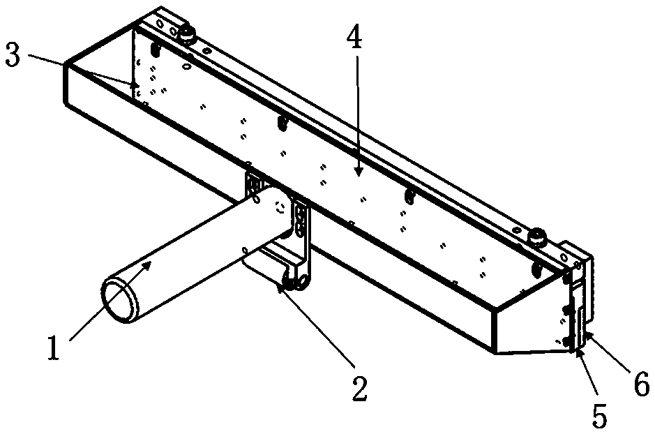
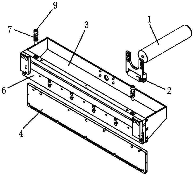
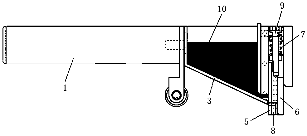
[0015] Such as Figure 1 to Figure 4 As shown, a squeegee used in the printing and textile industries is mainly composed of a handle 1, a guide roller 2, a glue tank 3, a flow regulating plate 4, a rubber baffle 5 and a scraper 6; the handle 1 is fixedly connected with the glue holding tank 3, the guide roller 2 is fixedly connected to the back of the glue holding tank 3 directly below the handle 1, the flow regulating plate 4 is fixedly connected to the front of the glue holding tank 3, and the front of the glue holding tank 3 A scraper 6 is fixedly connected to the bottom of the rubber tank 3, and a rubber baffle 5 is fixedly connected to the lower edge of the glue tank 3. The gap between the rubber baffle 5 and the scraper 6 forms a diversion groove for the rubber material 10 to flow out. 8. Two guide pillars 9 are arranged on the groove ...


PUM


Abstract

The invention discloses a glue frictioning device applied to printing and textile industries and an AB glue coating method. The glue frictioning device is mainly composed of a handle, a guide roll, aglue storage groove, a flow adjusting plate, a glue baffle and a scraping plate. The handle is fixedly connected with the glue storage groove. The guide roll is fixedly connected to the portion, located under the handle, of the back side of the glue storage groove. The flow adjusting plate is fixedly connected to the front side of the glue storage groove. The scraping plate is fixedly connected tothe bottom of the front side of the glue storage groove. The glue baffle is fixedly connected to the lower edge of the glue storage groove. A flow guide slot which can allow glue to flow out is formed by the gap between the glue baffle and the scraping plate. Each guide post is sleeved with a spring. According to the glue frictioning device, the glue storage groove is adopted to lengthen a groovetype glue outlet and to be combined with the scraping plate, glue adding can be achieved at a time, the glue surface can be formed at a time, the glue surface forming rate is high, and the glue surface is free of bubbles; through the design of the springs and the guide roll, down force of an operator and counter-acting force of the springs are balanced during glue frictioning, so that the glue surface is stresses more uniformly, and a film is formed more uniformly.

Description

technical field [0001] The invention belongs to a squeegee device in the field of clothing printing, and in particular relates to a squeegee used in printing and textile industries and a gluing method for AB glue. Background technique [0002] Most of the gluing methods in the prior art are roller-type and needle-tube-type gluing methods. The roller-type gluing method refers to applying the glue on the roller and rolling the glue, but this kind of gluing method will cause the glue to be picked up by the roller and then fall, which is prone to air bubbles. The needle-type gluing method is to inject glue into a container similar to a syringe, and the glue is extruded by squeezing the container, and can form strips during movement, but we need the glue to form a film, so it cannot meet the process requirements. AB glue is a kind of composite resin glue. The main component of AB glue is an active film-forming agent. It is a kind of glue that dries when water evaporates. The AB...

Claims


Application Information

Patent Timeline
IPC IPC(8): B05C17/00
CPCB05C17/00
Inventor 熊景芳宋国庆陈胤
Owner SHANGHAI TAIDU TECH CO LTD
Why Eureka
Try Eureka