Steel ladle gas-breathable upper water gap seat brick and method for controlling steel ladle to unload slag by same

A technology for nozzle seat bricks and ladles, which is applied in the direction of manufacturing tools, casting molten material containers, metal processing equipment, etc., can solve the problems of ineffective prevention, long length, and small diameter of air-permeable rods, so as to prevent air leakage of the device, Effects of preventing side leakage of gas and reducing production cost

Active Publication Date: 2018-07-13
NORTHEASTERN UNIV
View PDF14 Cites 4 Cited by
  • Summary
  • Abstract
  • Description
  • Claims
  • Application Information

AI Technical Summary

Problems solved by technology

This patent has the following deficiencies: the diameter of the ceramic venting rod is too small, which is not conducive to gas circulation, and cannot effectively prevent the problem of vortex (vortex) slag entrainment; it does not consider the influence of the drainage sinkhole on the slag of the ladle, and cannot target the drainage sinkhole The slag is caused by the proposed control measures; the number of breathable ceramic rods is too large and the length is too long, the production cost of the nozzle block is high, and it is not suitable for industrial production
This patent has the following deficiencies: the structure of the

Method used


Image

  • Steel ladle gas-breathable upper water gap seat brick and method for controlling steel ladle to unload slag by same
  • Steel ladle gas-breathable upper water gap seat brick and method for controlling steel ladle to unload slag by same
  • Steel ladle gas-breathable upper water gap seat brick and method for controlling steel ladle to unload slag by same

Examples


Embodiment 1

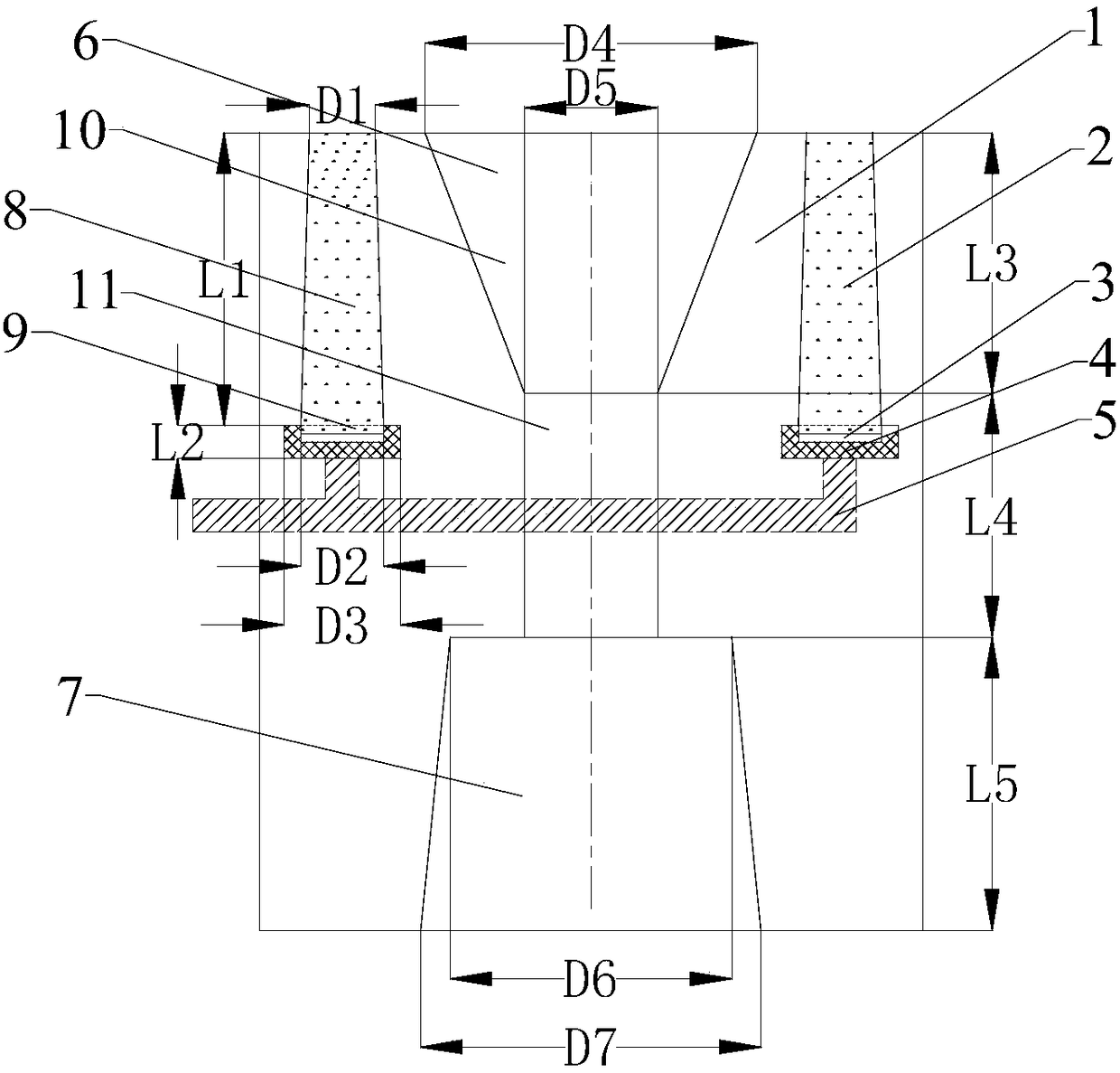
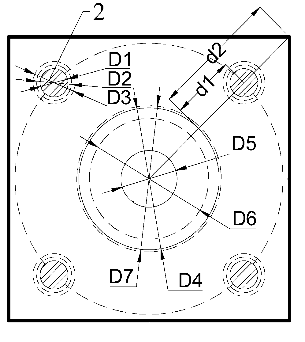
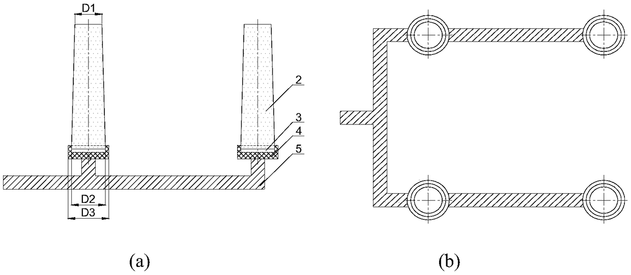
[0036] A kind of ladle breathable upper nozzle seat brick, such as figure 1 with Figure 4 As shown, it includes the ladle upper nozzle block body (1), vent plug (2), air chamber box (3), vent plug base (4), air blowing pipe (5), flow steel hole (6) and upper nozzle Mounting hole (7); the venting plug (2), air chamber box (3), venting plug base (4), flow steel hole (6) and upper nozzle installation hole (7) are all arranged on the ladle upper nozzle seat brick Inside the main body (1), the main body of the blowing pipe (5) is set inside the ladle upper nozzle block body (1), and passes through the side of the ladle upper nozzle block body (1); the flow steel hole (6) is located on the upper The top of the nozzle installation hole (7) is connected with it, and the flow steel hole (6) and the upper nozzle installation hole (7) run through the ladle upper nozzle block body (1) from top to bottom as a whole; ) is provided with a vent plug (2), an air chamber box (3), a vent plug...

Embodiment 2

[0049] A kind of ladle breathable upper nozzle seat brick, such as Figure 1-Figure 3 shown. Including the ladle upper nozzle block body (1), vent plug (2), air chamber box (3), vent plug base (4), air blowing pipe (5), flow steel hole (6) and upper nozzle installation hole ( 7); the vent plug (2), the air chamber box (3), the vent plug base (4), the flow steel hole (6) and the upper nozzle installation hole (7) are all arranged on the ladle upper nozzle block body (1 ) inside, the main body of the blowing pipe (5) is set inside the ladle upper nozzle block body (1), and passes through the side of the ladle upper nozzle block body (1); the flow steel hole (6) is located in the upper nozzle installation hole (7) above and connected with it, the flow steel hole (6) and the upper nozzle installation hole (7) run through the ladle upper nozzle block body (1) from top to bottom as a whole; set around the flow steel hole (6) Vent plug (2), air chamber box (3), vent plug base (4) a...

Embodiment 3

[0065] A kind of ladle breathable upper nozzle seat brick, such as Figure 1-Figure 3 As shown, it includes the ladle upper nozzle block body (1), vent plug (2), air chamber box (3), vent plug base (4), air blowing pipe (5), flow steel hole (6) and upper nozzle Mounting hole (7); the venting plug (2), air chamber box (3), venting plug base (4), flow steel hole (6) and upper nozzle installation hole (7) are all arranged on the ladle upper nozzle seat brick Inside the main body (1), the main body of the blowing pipe (5) is set inside the ladle upper nozzle block body (1), and passes through the side of the ladle upper nozzle block body (1); the flow steel hole (6) is located on the upper The top of the nozzle installation hole (7) is connected with it, and the flow steel hole (6) and the upper nozzle installation hole (7) run through the ladle upper nozzle block body (1) from top to bottom as a whole; ) is provided with a vent plug (2), an air chamber box (3), a vent plug base ...


PUM

PropertyMeasurementUnit
Port diameteraaaaaaaaaa
Heightaaaaaaaaaa
Heightaaaaaaaaaa

Abstract

The invention discloses a steel ladle gas-breathable upper water gap seat brick and a method for controlling a steel ladle to unload slag by same. The steel ladle gas-breathable upper water gap seat brick comprises a steel ladle upper water gap seat brick body, a gas-breathable plug, a gas chamber box, a gas-breathable plug base, a gas-blowing pipeline, a runner hole and an upper water gap mounting hole. The control method comprises the following steps of: 1) putting the steel ladle upper water gap seat brick at a bottom tap hole of the steel ladle, and enabling the gas-blowing pipeline whichgets out from the steel ladle gas-breathable upper water gap seat brick to communicate with a gas path pipeline; 2) when a ratio of height of molten steel in the steel ladle to height of the steel ladle is 1 to (16-35), blowing inert gas into the molten steel through the gas-blowing pipeline, forming a circular concave region free of a slag layer on the surface of molten steel, and restraining steel ladle from unloading slag; and 3) when the steel ladle has slag unloading, closing a steel ladle water hole, and stopping blowing gas through the gas-blowing pipeline. According to the steel ladlegas-breathable upper water gap seat brick disclosed by the invention, argon gas is blown in at a last stage of casting, the circular convex region free of the slag layer is formed on the surface of molten steel, steel ladle slag unloading caused by conflux vortex and drainage sunken pits is effectively restrained, casting margin, which is reduced by 35% or more in comparison with existing castingmargin, of molten steel in the steel ladle is reduced.

Description

technical field [0001] The invention belongs to the field of continuous casting of iron and steel, and in particular relates to a ladle breathable upper nozzle seat brick and a method for controlling ladle slag. Background technique [0002] The control of ladle slag in the continuous casting process has always been a common problem in the industry. At the end of pouring, the molten steel in the ladle produces slag due to reasons such as confluence vortex, drainage sinkhole, etc., resulting in increased inclusions and quality defects in the slab. Usually, the slag control system is used to control the slag, that is, the nozzle is closed immediately when the ladle is detected to be slag during the pouring process, but this will cause a large amount of molten steel in the ladle to be poured, and the metal yield will be reduced. [0003] Chinese patent document CN104028739A (Patent No.: 201410274221) discloses a ladle ventilating upper nozzle block and its method for controllin...

Claims


Application Information

Patent Timeline
IPC IPC(8): B22D41/58
CPCB22D41/58
Inventor 郑淑国邹琦朱苗勇
Owner NORTHEASTERN UNIV
Why Eureka
Try Eureka