
Automatic groove cutting system and cutting method based on three-dimensional vision and model matching

A technology of automatic cutting and model matching, applied in welding equipment, gas flame welding equipment, metal processing equipment, etc., can solve problems such as inability to automatically cut, and achieve the effect of improving automation and intelligence

Active Publication Date: 2018-07-13
BEIJING INSTITUTE OF PETROCHEMICAL TECHNOLOGY +1
View PDF5 Cites 29 Cited by
  • Summary
  • Abstract
  • Description
  • Claims
  • Application Information

AI Technical Summary

Problems solved by technology

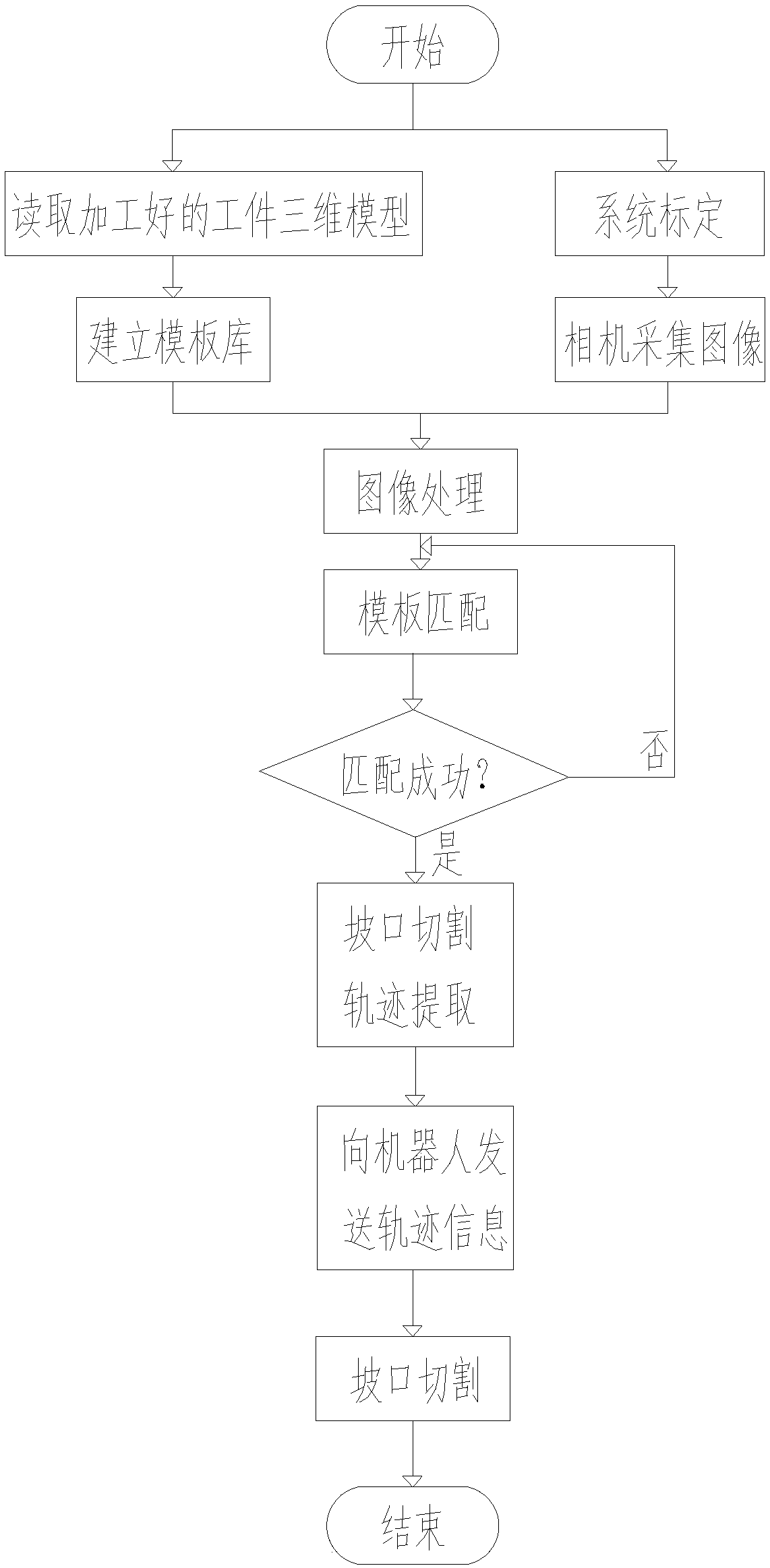
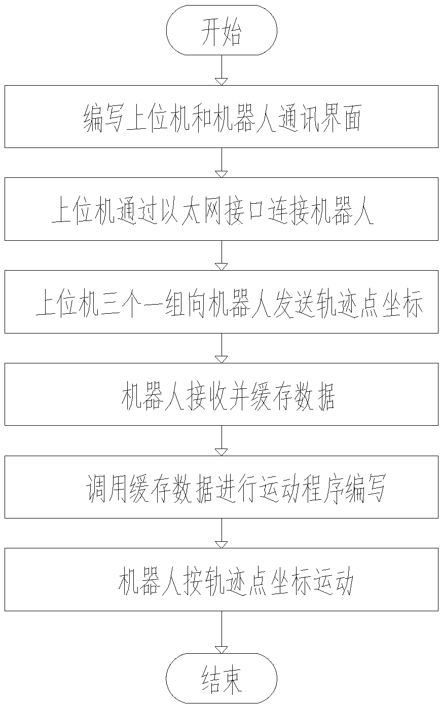
[0004] The object of the present invention is to provide a bevel automatic cutting system and cutting method based on three-dimensional vision and model matching. The workpiece is scanned by a 3D camera to obtain an image of the workpiece without bevel, and the image and the template library with bevel The three-dimensional model of the workpiece is matched. After the matching is successful, according to the comparison information, the processing track information of the groove cutting is obtained, and then the robot is controlled to complete the groove cutting, so as to solve the existing technology that cannot automatically realize the automatic processing of different workpieces and different types of grooves. cutting technical issues

Method used


Image

  • Automatic groove cutting system and cutting method based on three-dimensional vision and model matching
  • Automatic groove cutting system and cutting method based on three-dimensional vision and model matching
  • Automatic groove cutting system and cutting method based on three-dimensional vision and model matching

Examples


Embodiment Construction

[0034] In order to make the purpose, technical solution and advantages of the present invention clearer, the technical solution of the present invention will be described in detail below. Apparently, the described embodiments are only some of the embodiments of the present invention, but not all of them. Based on the embodiments of the present invention, all other implementations obtained by persons of ordinary skill in the art without making creative efforts fall within the protection scope of the present invention.

[0035] The invention provides an automatic groove cutting system based on three-dimensional vision and model matching, which integrates vision, optics and electromechanical equipment, including a 3D vision subsystem, a host computer, a motion control system, a cutting robot and cutting equipment, and a 3D vision subsystem. The system is connected with the signal of the host computer, the signal of the host computer is connected with the motion control system, th...


PUM


Abstract

The invention provides an automatic groove cutting system and a cutting method based on three-dimensional vision and model matching, and relates to the technical filed of groove processing equipment.The automatic groove cutting system based on three-dimensional vision and model matching comprises a 3D vision subsystem, a host computer, a motion control system, a cutting robot and a cutting device. The 3D vision subsystem is connected with the host computer in a signal mode, the host computer is connected with the motion control system in a signal mode, the cutting device is arranged on the cutting robot, and the motion control system is electrically connected with the cutting robot. The automatic groove cutting method uses a 3D vision system and an image processing software and is based on an image processing algorithm, and the mapping between a robot, the 3D vision system and a workpiece coordinate system is realized by using a 3D camera internal and external parameter calibration algorithm, a three-point calibration method and an attitude matching algorithm . Different workpieces and groove types can be automatically cut, groove quality is good and efficiency is high, and automation and intelligence of the groove cutting system are improved.

Description

technical field [0001] The present invention relates to the technical field of bevel processing equipment, in particular to an automatic bevel cutting system and cutting method based on three-dimensional vision and model matching. Through image acquisition and image processing, the workpiece is matched with the template to obtain processing track information, and then the robot is controlled. Motion for beveling. Background technique [0002] In the processing and production process of large-scale equipment such as shield machines, the amount of groove processing of parts is very large. At present, for small batches, non-linear and other special-shaped grooves, manual or semi-automatic cutting methods are mostly used, and there are a series of problems such as poor groove cutting quality, unstable quality, low groove processing efficiency, and high cost; and the groove quality Poor or unstable processing quality not only affects the precision of the part itself, but also se...

Claims


Application Information

Patent Timeline
IPC IPC(8): B23K7/00B23K7/10
CPCB23K7/00B23K7/10
Inventor 曹莹瑜薛龙梁亚军董俊杰王国帅黄军芬黄继强
Owner BEIJING INSTITUTE OF PETROCHEMICAL TECHNOLOGY
Learn More