Quick die change device and foam molding machine with quick die change device

A molding machine and fast technology, applied in the field of mechanical equipment, can solve the problems of inability to adopt the first assembly method, difficult to assemble the mold support plate, and inability to assemble

Pending Publication Date: 2018-07-13
烟台裕华液力机械有限公司
View PDF0 Cites 8 Cited by
  • Summary
  • Abstract
  • Description
  • Claims
  • Application Information

AI Technical Summary

Problems solved by technology

Therefore, the workshop site occupies a large area. When the spacing and site space are not allowed, the first assembly method cannot be adopted.
[0007] Even if the conditions required for the second assembly method can be met, if the structure of the mold is relatively simple, the time spent in changing the mold will be relatively shor

Method used


Image

  • Quick die change device and foam molding machine with quick die change device
  • Quick die change device and foam molding machine with quick die change device
  • Quick die change device and foam molding machine with quick die change device

Examples


Embodiment 1

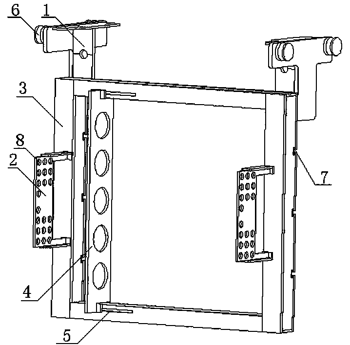
[0031] The quick mold change device 18 in this embodiment is used for quick mold change, saving mold change time and improving mold change efficiency. The quick mold change device 18 includes a mold change frame, a connector one 1, and a connector two 2, wherein the mold change frame is a hollow frame structure inside, and the connector one 1 and the connector two 2 are all located on the mold change frame 3 On the connecting piece 1, a sliding piece is provided.

[0032] Connecting piece 1 is used to assemble the mold changing frame on the foam molding machine frame 12, connecting piece 2 is used to connect the material gun to facilitate feeding, connecting piece 1 and connecting piece 2 are installed on the mold changing on the frame 3, and there are multiple ones installed, but it is necessary to ensure that the multiple connectors one 1 are located on the opposite side of the same direction of the mold change frame 3, which is convenient for hoisting, and the multiple conn...

Embodiment 2

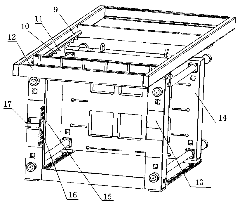
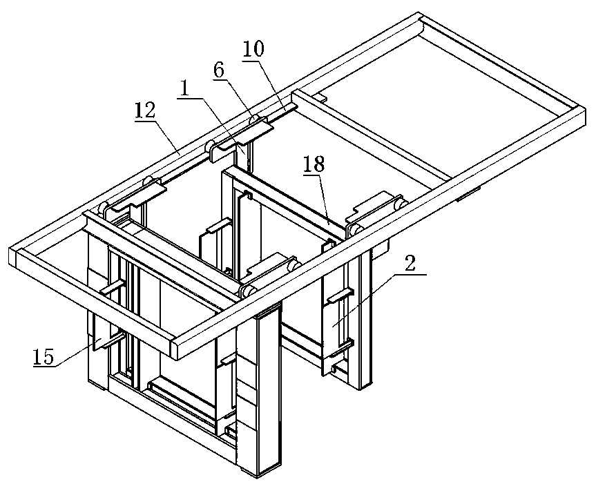
[0038] In this embodiment, the quick mold change frame provided by Embodiment 1 is adopted, and the structure of the quick mold change frame is not described in detail, and the structure adopted for the installation of the quick mold change frame and the frame 12 of the foam molding machine is further described. In the foam forming machine of the present embodiment, the frame 12 has a structure such as figure 2As shown, it includes a quick mold change device 18, a mold fixing frame 13, and a mold moving frame 14 positioned on the frame 12 of the foam molding machine, wherein the mold fixing frame 13 is fixed on the foam molding machine frame 12, the The mold moving frame 14 is movably connected on the foam molding machine frame 12 and moves forward and backward relative to the mold fixing frame 13. The quick mold changing device 18 is freely installed between the mold fixing frame 13 and the mold moving frame 14. The mold device 18 comprises a die changing frame, a connector ...


PUM


Abstract

The invention belongs to the field of mechanical equipment, and particularly relates to a quick die change device and a foam molding machine with the quick die change device. The quick die change device comprises a die change frame, connecting pieces I and connecting pieces II, wherein the die change frame is hollow inside; the connecting pieces I and the connecting pieces II are positioned on thedie change frame; and sliding parts are arranged on the connecting pieces I. The foam molding machine with the quick die change device comprises the quick die change device, a die fixing frame and adie moving frame on a foam molding machine rack, wherein the die fixing frame is fixed to the foam molding machine rack; and the die moving frame is movably connected to the foam molding machine rackand moves front and back relative to the die fixing frame. According to the quick die change device and the foam molding machine with the quick die change device, a die can be changed outside a machine body of the foam molding machine, change of the die is facilitated, time is saved, production efficiency is improved, and operation is simple.

Description

technical field [0001] The invention belongs to the field of mechanical equipment, and in particular relates to a quick mold changing device and a foam molding machine with the quick mold changing device. Background technique [0002] The foam molding machine is the main molding equipment for making thermoplastics or thermosetting plastics into various shapes of plastic products using plastic molding molds. The main structure of the foam molding machine is generally composed of the fixed frame of the male mold, the movable frame of the female mold, and the fixed frame of the hydraulic or air pressure or electric device. There are generally two ways to assemble the mold to the fixed frame of the convex mold and the movable frame of the concave mold. The first way is to assemble it outside the foam molding machine. After assembling the required mold and mold-related accessories, the overall Machine assembly; the second way is to assemble on the foam molding machine, first ass...

Claims


Application Information

Patent Timeline
IPC IPC(8): B29C44/02B29C44/58B29C44/34
CPCB29C44/02B29C44/35B29C44/58
Inventor 孙佳祺金永祚
Owner 烟台裕华液力机械有限公司
Why Eureka
Try Eureka