
Preformed hole sleeve fixing frame

A technology for reserving holes and fixing frames, which is applied in the direction of pipe supports, pipes/pipe joints/fittings, mechanical equipment, etc., which can solve the problems of large hole position deviation and casing offset, etc., to achieve long service life and ensure stability Effect

Active Publication Date: 2018-07-13
CHINA MCC5 GROUP CORP
View PDF5 Cites 2 Cited by
  • Summary
  • Abstract
  • Description
  • Claims
  • Application Information

AI Technical Summary

Problems solved by technology

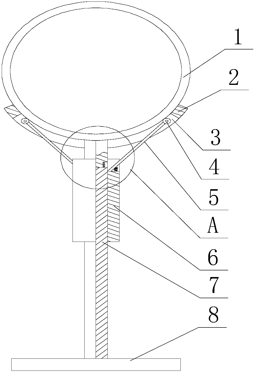
Aiming at the defect that the existing concrete wall is easy to shift the casing and the position of the hole is relatively large due to the treatment of the reserved hole when pouring the concrete wall, the applicant designed a casing fixing frame specially used for the reserved hole, through The stable support of the support plate to the casing as a whole, and the adjustment and buffering of the radial stress on the casing by the connecting rod, thereby ensuring that the position of the casing remains stable, and on the premise that the casing can be quickly taken out after the concrete is dry, it can be formed. The hole matches the set value;

Method used


Image

  • Preformed hole sleeve fixing frame
  • Preformed hole sleeve fixing frame

Examples


Embodiment 1

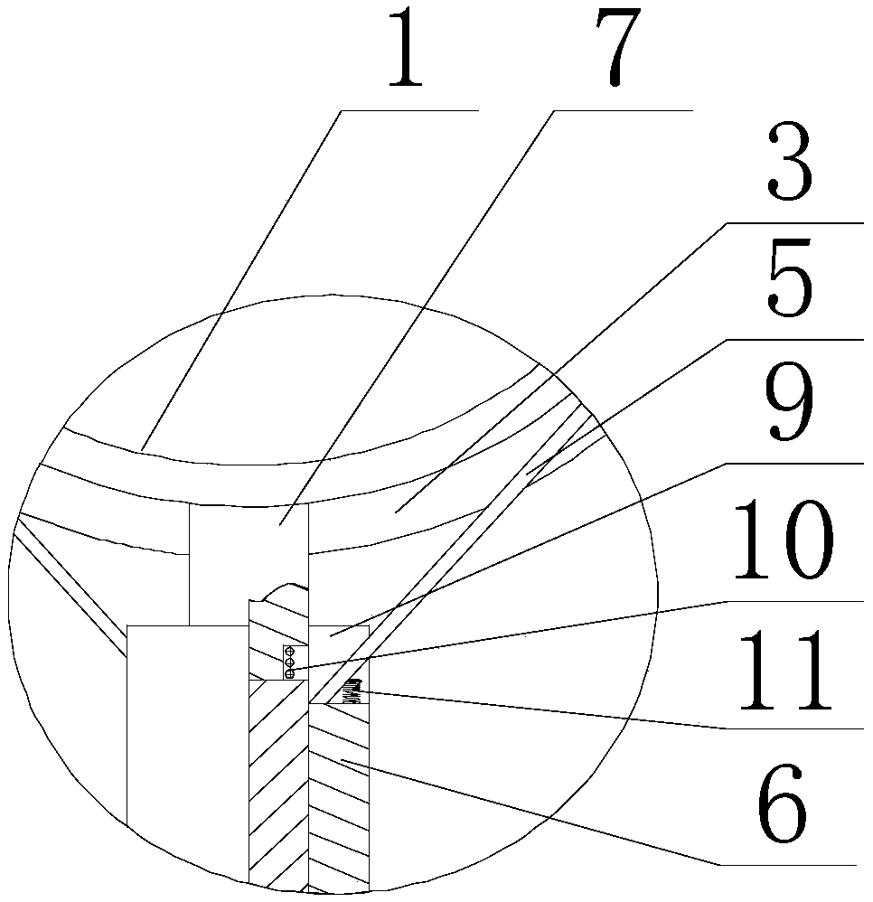
[0022] Such as Figure 1~2 As shown, the present embodiment includes a base 8 and a column 7 fixed on the base 8. A support plate 2 matching the outer peripheral wall of the casing 1 is fixed on the upper end of the column 7. On the upper section of the column 7 The limiting cylinder 6 is fixed on the outer peripheral wall, and two symmetrically distributed openings 9 are opened on the upper end surface along the axis of the limiting cylinder 6, and the bottom of each opening 9 is hinged with the lower end of the connecting rod 5. The bottom of the opening 9 is also provided with a spring I11, and the upper end of the spring I11 is connected to the outer wall of the connecting rod 5, and an arc-shaped chute 3 is opened in the middle of the support plate 2, and the upper end of the connecting rod 5 extends upward and is placed on the slide. In the groove 3 , and at the upper end of the connecting rod 5 , a roller 4 is arranged, and the roller 4 is in contact with the outer peri...

Embodiment 2

[0025] Such as Figure 1~2 As shown, the column 7 in this embodiment includes an upper section and a lower section, the upper end of the upper section is in contact with the outer wall of the casing 1, the side wall of the upper section is connected with the side wall of the chute 3, and the limit cylinder 6 is fixed on the lower section The upper end of the upper end of the limit cylinder 6 is H, the horizontal height of the upper end of the lower section is h, and H>h is satisfied, and a connecting column is provided on the lower end of the upper section, and The outer diameter of the connecting column is smaller than the outer diameter of the upper section, and a spring II10 is sheathed on the outer peripheral wall of the connecting column. When the support plate 2 contacts the casing 1, both the spring I11 and the spring II10 are compressed . When concrete is poured into the steel frame, the direction of concrete injection cannot be determined, that is, one end of the sle...


PUM


Abstract

The invention discloses a preformed hole sleeve fixing frame. The preformed hole sleeve fixing frame comprises a base and a stand column. Supporting plates matched with the outer circumferential wallof a sleeve are fixed to the upper end of the stand column. A limiting sleeve is fixed to the outer circumferential wall of the upper section of the stand column. Two symmetrical openings are formed in the upper end face of the limiting sleeve in the axial direction of the limiting sleeve. The bottom of each opening is hinged to the lower end of a connecting rod. A spring I is arranged at the bottom of each opening. The upper end of the spring I is connected with the outer wall of the corresponding connecting rod. An arc-shaped sliding groove is formed in the middle of each supporting plate. The upper end of each connecting rod extends upwards and then is arranged in the corresponding sliding groove. The upper end of each connecting rod is provided with a rolling wheel. The rolling wheelsmake contact with the outer circumferential wall of the sleeve. Through stable supporting of the supporting plates on the whole sleeve and adjustment buffering of the connecting rods on radial stressborne by the sleeve, it is guaranteed that the position of the sleeve is kept stable. On the premise that the sleeve is taken out quickly and conveniently after drying and solidification of concrete,it is guaranteed that formed holes are matched with a set value.

Description

technical field [0001] The invention relates to the field of building construction, in particular to a casing fixing frame with reserved holes. Background technique [0002] The composition of modern buildings is more and more multi-functional, multi-configuration, and large-scale, and the structural types are mostly combined with reinforced concrete for decoration. The diversification of functions has increased the proportion of water, electricity, heating, and ventilation projects. increased in importance. The reservation of holes, especially the pre-buried holes through concrete walls, is also a very important issue. If it is not handled properly, it will bring great losses to civil engineering and installation. The traditional method is to fix steel bars with steel pipes or plastic pipes. The nozzles are open, and the concrete is easily displaced during pouring. The position of the holes is relatively large, and the concrete is easy to enter the nozzles. It is not suita...

Claims


Application Information

Patent Timeline
Patent Type & Authority Applications(China)
IPC IPC(8): F16L3/02F16F15/04
CPCF16F15/04F16L3/02
Inventor 关敏刘海江
Owner CHINA MCC5 GROUP CORP
Learn More