

High-power beam trap
A high-power, reflective surface technology, used in instruments, laser welding equipment, optics, etc., can solve the problem of expensive assembly and achieve high absorption
- Summary
- Abstract
- Description
- Claims
- Application Information
AI Technical Summary
Problems solved by technology
Method used
Image

Examples
Embodiment Construction
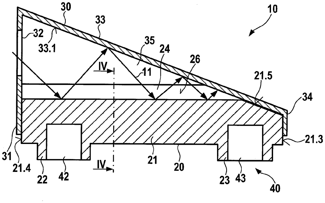
[0025] figure 1 The high power beam trap 10 according to the invention is shown in a side sectional view. It has an absorber 20 which is covered by a housing 30 .
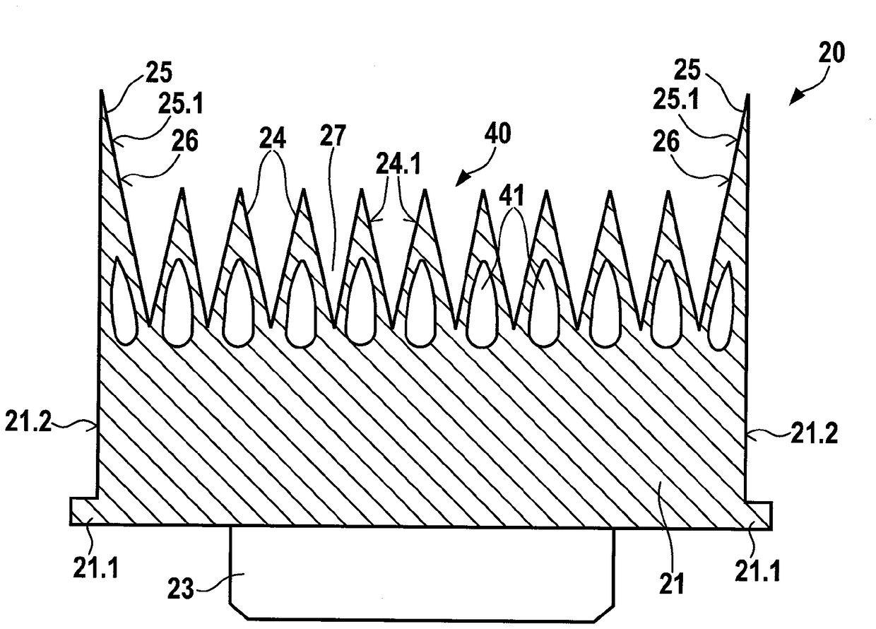
[0026] The absorbent body 20 has a base body 21 on which wedge-shaped ribs 24 are molded, as from figure 2 can be found in more detail. The surface of the wedge-shaped ribs 24 forms the absorption surface 26 . Opposite the wedge-shaped ribs 24 , an inlet connection 22 and an outlet connection 23 are formed on the base body 21 . The inlet connecting pipe 22 forms the coolant inlet 42 and the outlet connecting pipe 23 forms the coolant outlet 43 of the cooling circuit 40 .
[0027] The housing 30 covers the absorber 20 on the sides of the wedge-shaped ribs 24 . Housing cover 33 of housing 30 is oriented obliquely to absorption surface 26 . Facing the wedge-shaped rib 24, it forms the reflective surface 33.1. The front side 31 , the housing closure 34 and the two opposite side walls 35 extend from the housing ...
PUM
 Abstract
Description
Claims
Application Information