Motion platform of lithography machine, micro-motion platform and control method thereof

A motion platform and micro-motion technology, applied in opto-mechanical equipment, micro-lithography exposure equipment, optics, etc., can solve the problems of voice coil motor insufficiency, high power consumption, and unable to replace the voice coil motor actuator.

Active Publication Date: 2020-10-27
FUDAN UNIV
View PDF3 Cites 0 Cited by
  • Summary
  • Abstract
  • Description
  • Claims
  • Application Information

AI Technical Summary

Problems solved by technology

[0005] 1. Linear voice coil motor has the characteristics of low disturbance and high response frequency. It is the best choice for precise control of position, speed and force. It is widely used as the driving mechanism of micro-motion table, but its disadvantages are low efficiency and power consumption. Big
High acceleration requires a high-thrust motor. In the current state that has almost reached its limit, if the next-generation lithography micro-motion table is still driven by a voice coil motor to achieve greater thrust, its size will become very large and it will generate heat. The problem will directly affect the measurement accuracy of the laser interferometer, and the wiring of the supporting cooling water pipes will become very difficult, making the voice coil motor unable to meet the requirements of the micro-motion stage of the next generation lithography machine
[0006] 2. Lorentz force magnetic levitation planar motor may realize the integration of coarse and fine motion, and can realize the large thrust required by high acceleration, but due to the large fluctuation of the motor constant and the difficulty of accurate measurement and compensation, it cannot achieve nanometer precision Requirements, it is expected that voice coil motors will not be replaced for a long time in the future
However, the nonlinear characteristics of the motor make it difficult to control. The uniform motion and positioning accuracy caused by nonlinear hysteresis change with the position, and the repeatability is poor. For applications with micron-level precision, its influence can be ignored, but for Micro-motion table for lithography machine with nanometer precision. If these problems are not solved, it will make it impossible to replace the voice coil motor as the actuator for driving the micro-motion table.
[0008] At present, there is no good drive mechanism or control technology for the next-generation lithography machine micro-table that can meet the requirements of high acceleration, high speed and high-precision movement in lithography.

Method used


Image

  • Motion platform of lithography machine, micro-motion platform and control method thereof
  • Motion platform of lithography machine, micro-motion platform and control method thereof
  • Motion platform of lithography machine, micro-motion platform and control method thereof

Examples


Embodiment 1

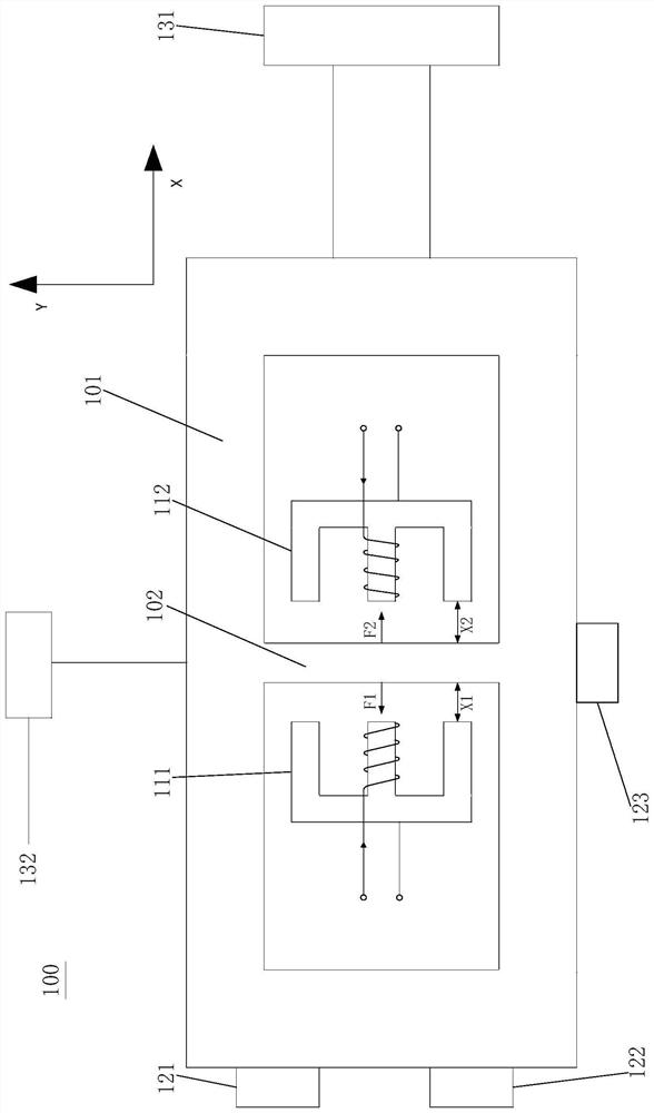
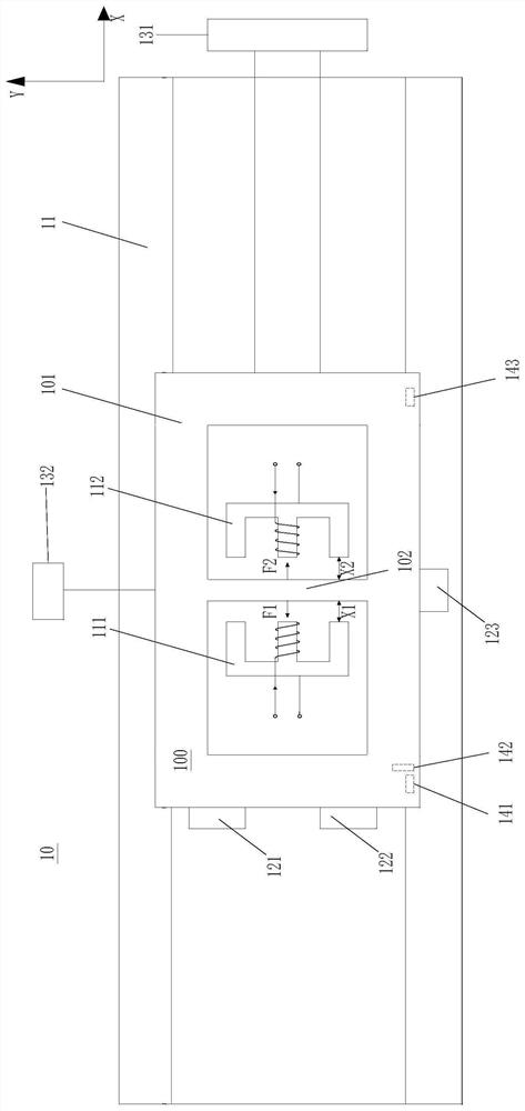
[0049] according to figure 1 , the figure shows a three-degree-of-freedom micro-motion platform 100, including a first micro-motion stage 101, two reluctance motors 111 and 112, three voice coil motors 121, 122 and 123, and two laser interferometers 131 and 132. The reluctance motors 111 and 112 share an I-type center 102 as a mover, and the two electromagnets of the reluctance motors 111 and 112 are symmetrically arranged on both sides of the I-type center 102, and the I-type center 102 and the first micro-motion Platform 101 has an integrated structure. The voice coil motors 121 and 122 are arranged on the same side of the first micro-motion table 101 , and the voice coil motor 123 is arranged on an adjacent side of this side. The laser interferometers 131 and 132 are respectively arranged on adjacent two sides of the first micro-motion stage 101 .

[0050] The reluctance motors 111 and 112 can push the first micro-motion stage 101 along the X coordinate axis (coordinate ...

Embodiment 2

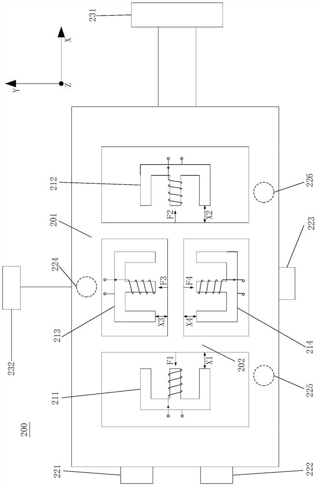
[0076] according to figure 2 , the figure shows a six-degree-of-freedom micro-motion platform 200, including a second micro-motion stage 201, four reluctance motors 211, 212, 213 and 214, six voice coil motors 221, 222, 223 and 224, 225, 226, and two laser interferometers 231 and 232. The reluctance motors 211, 212, 213 and 214 share an H-shaped center 202 as a mover, and the four electromagnets of the reluctance motors 211, 212, 213 and 214 are symmetrically arranged on four sides of the H-shaped center 202. The type center 202 and the second micro-motion table 201 are integrally structured. The setting of the voice coil motors 221, 222, 223 is the same as that of the voice coil motors 121, 122, 123 in the first embodiment. The linear movement and rotational movement and positioning of the platform 200 along the direction of six degrees of freedom (as shown in Figure 2). Other structural designs and control methods of the six-degree-of-freedom micro-motion platform 200 ar...


PUM


Abstract

The invention discloses a photoetching machine movement platform and a micro movement platform thereof, and a control method of the micro movement platform. According to the present invention, a reluctance motor and a high-precision voice coil motor are symmetrically distributed and are combined to form the structure of the micro movement platform, wherein the reluctance motor provides high thrusting force required by high acceleration, and the voice coil motor provides high-precision positioning ability, such that the use of the dual motor drive mode integrates the advantages of both motors while the shortcomings of both motors are avoided; according to the control scheme, the double-channel double-motor control mode is used, the feed forward channel comprises the open-loop controlled reluctance motor, the high thrusting force required by the high acceleration / deceleration process of the micro movement platform can be ensured through the high thrusting force property of the open-loopcontrolled reluctance motor, and the bandwidth controlled by the current loop comprising the reluctance motor and the power amplifier is generally greater than the bandwidth controlled by the positionclosed loop so as to easily achieve rapid tracking; and by using the voice coil motor as the feedback control, the precision during the constant-speed movement and the positioning can further be ensured.

Description

technical field [0001] The invention belongs to the field of integrated circuit chip manufacturing, and in particular relates to a motion platform of a photolithography machine, a micro-motion platform and a control method thereof. Background technique [0002] According to Moore's Law, the integration level of integrated circuit chips can be increased by four times every three years, and in recent years there has been a tendency to exceed this law. In the process of rapid development of integrated circuits, lithography equipment has played a basic supporting role. In the scanning lithography machine, on the one hand, the exposure imaging is completed in high-speed motion, and its scanning and positioning accuracy directly affect the imaging accuracy and overlay accuracy of the lithography machine, so its scanning and positioning accuracy need to reach the nanometer level precision. On the other hand, the acceleration and speed of motion directly affect the yield, so high ...

Claims


Application Information

Patent Timeline
Patent Type & Authority Patents(China)
IPC IPC(8): G03F7/20
CPCG03F7/70716G03F7/70725G03F7/70758
Inventor 陈庆生杨晓峰徐云浪吴立伟
Owner FUDAN UNIV
Why Eureka
Try Eureka