
Flying robot arm based on sliding mode PID (proportion integration differentiation) control

A technology of mechanical arm and sliding mode, which is applied in the aviation field and can solve problems such as poor robustness and poor anti-interference

Inactive Publication Date: 2018-07-13
NANJING UNIV OF INFORMATION SCI & TECH
View PDF4 Cites 8 Cited by
  • Summary
  • Abstract
  • Description
  • Claims
  • Application Information

AI Technical Summary

Problems solved by technology

[0005] The present invention proposes a new type of sliding mode PID control, which improves the problems of poor anti-interference and poor robustness in traditional PID control and chattering problems in sliding mode control

Method used


Image

  • Flying robot arm based on sliding mode PID (proportion integration differentiation) control
  • Flying robot arm based on sliding mode PID (proportion integration differentiation) control
  • Flying robot arm based on sliding mode PID (proportion integration differentiation) control

Examples


Embodiment Construction

[0020] The technical solution of the present invention will be described in detail below in conjunction with the accompanying drawings.

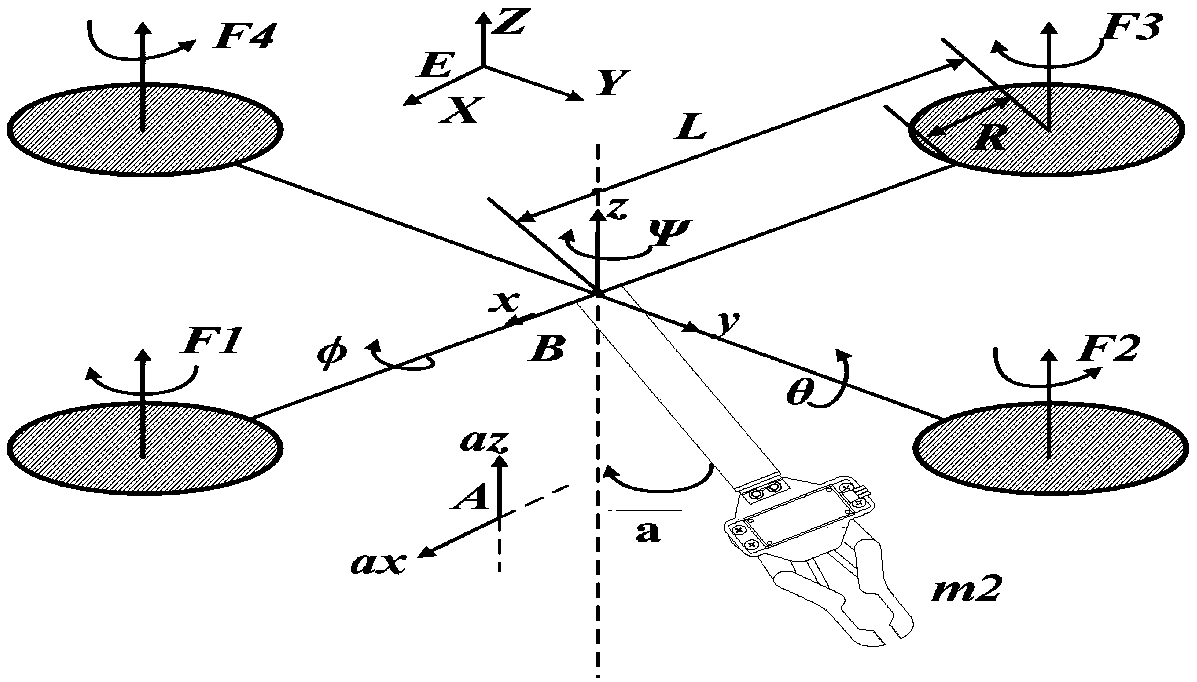
[0021] figure 1 It is a structural diagram of a quadrotor equipped with a robotic arm. For the convenience of modeling and analysis, three coordinate systems have been established—the earth coordinate system E-XYZ, the quadrotor coordinate system B-xyz, and the robotic arm coordinate system A-ax,az. Among them, the E coordinate system can be regarded as an inertial coordinate system, while the B coordinate system is a follow-up coordinate system and the origin of B is located at the centroid of the quadrotor, and the equipped robotic arm is located below the quadrotor.

[0022] Table 1 Four-rotor structure parameter list

[0023]

[0024] Select the generalized coordinate vector q=(φ,θ,ψ,x,y,z,a) T , pseudo velocity vector p=(p,q,r,u,v,w,b) T , based on the Euler-Poincaré equation to establish the dynamic model of the quadrotor UAV [...


PUM


Abstract

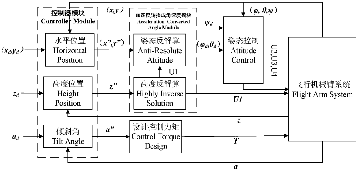
The invention discloses a flying robot arm based on a sliding mode PID (proportion integration differentiation) control. Considering an underactuated problem of a quadrotor, that is, 4 inputs control6 degrees of freedom, coupling characteristics of the system can be made full use of to establish a mathematical relationship of an attitude angle and position with height control amount U1, and thus,the purpose of trajectory tracking is achieved by the controlling of the attitude angle and the position height. With the system divided into a full drive subsystem and an underactuated subsystem, not only can flight function of a quadrotor aircraft be achieved, but also the robot arm is capable of grabbing in the air. Furthermore, the flying robot arm based on the sliding mode PID control has the advantages of being capable of being quickly and accurately controlled according to different motion of objects, and realizing stable tracking and grabbing for objects in different states.

Description

technical field [0001] The invention belongs to the technical field of aviation aircraft design, and in particular relates to a highly efficient, multi-purpose, quadrotor aircraft-based carrying manipulator that can realize both the air flight function of the quadrotor aircraft and the grasping function of the manipulator in the air. The different movements of objects can quickly and accurately control the robotic arm, and can realize stable tracking and grasping of objects in different states. Background technique [0002] Quadrotor aircraft is an aircraft that uses four rotors as flight engines to fly in the air. Since the beginning of the 20th century, electronic technology has developed rapidly, and quadcopters have begun to be miniaturized and integrated with artificial intelligence, making their development tend to be unmanned aerial vehicles and intelligent robots. The quadcopter not only realizes the flight performance of the vertical lift of the helicopter, but als...

Claims


Application Information

Patent Timeline
IPC IPC(8): G05B11/42
CPCG05B11/42
Inventor 刘云平周玉康黄希杰杨健康
Owner NANJING UNIV OF INFORMATION SCI & TECH
Learn More