Bus-based distributed movement control system and bus-based distributed movement control method

A motion control system and motion control technology, applied in the general control system, control/regulation system, program control, etc., can solve the cost and performance pressure of the controller 100, the reduction of the accuracy and performance of the controller 100, and the control error of the slave station 101 and other problems, to achieve the effect of increased and reduced calculation, low cost, and reduced control cycle

Active Publication Date: 2018-07-13
SHENZHEN VMMORE CONTROL TECH
View PDF10 Cites 7 Cited by
  • Summary
  • Abstract
  • Description
  • Claims
  • Application Information

AI Technical Summary

Problems solved by technology

[0004] First of all, the controller 100 needs to perform a large number of position calculations for each slave station 101. This calculation must be performed in each control cycle. As the number of slave stations 101 mounted on the bus increases, the amount of calculation will increase linearly. Doubling, will eventually exceed the computing power of the controller 100, in order to solve this problem, we can only continuously upgrade the performance of the processor;
[0005] Secondly, in order to complete a large number of position calculations, the controller 100 can only increase the control cycle, and the accuracy and performance of the controller 100 will be greatly reduced; since the controller 100 will maintain position calculations, bus masters and PLC logic at the same time, the bus allocation Insufficient hardware resources will increase the error probability of the bus, resulting in errors in the control of the slave station 101;
[0006] In addition, despite the rapid development of semiconductor technology and the increasing computing power of embedded processors, in many application scenarios, the number of slave stations 101 is large, and the motion control calculation of slave stations 101 consumes a large amount of processor resources. , in order to solve this problem, only the means of upgrading the performance of the processor or increasing the control period can be adopted, which puts great pressure on the cost and performance of the controller 100

Method used


Image

  • Bus-based distributed movement control system and bus-based distributed movement control method
  • Bus-based distributed movement control system and bus-based distributed movement control method

Examples


Embodiment Construction

[0022] The present invention will be described in more detail below in conjunction with the accompanying drawings and embodiments.

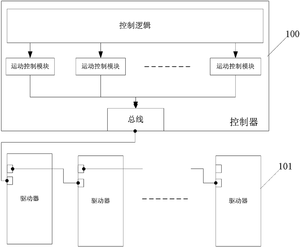
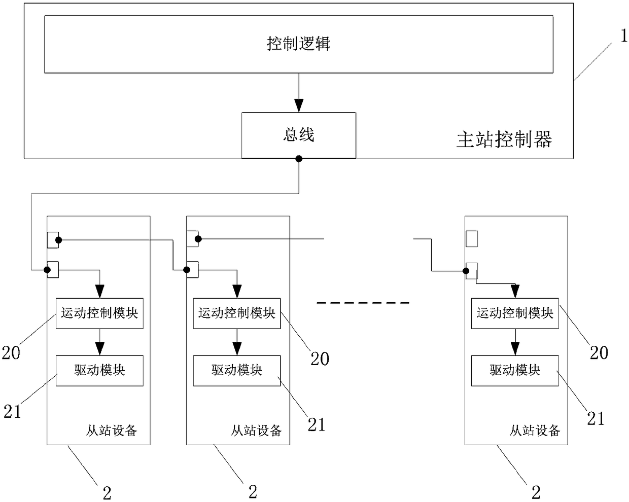
[0023] The invention discloses a bus-based distributed motion control system, please refer to figure 1 , which includes a master controller 1 and a plurality of slave devices 2, wherein:

[0024] The master station controller 1 is used to generate motion control parameters and send the motion control parameters;

[0025] The master controller 1 is connected to a plurality of slave devices 2 through a bus, the slave devices 2 are used to receive motion control parameters sent by the master controller 1, and the slave devices 2 are used to control The parameter calculates the real-time position data, speed data and / or torque data of the motor, and drives the motor to run.

[0026] In the above system, after the master station controller 1 generates the motion control parameters, it sends the motion control parameters to the specified slave statio...


PUM


Abstract

The invention discloses a bus-based distributed movement control system which comprises a master station controller and a plurality of slave station facilities. The master station controller is used for generating and transmitting movement control parameters; the master station controller is connected with the multiple slave station facilities in bus modes, and the slave station facilities are used for receiving the movement control parameters transmitted by the master station controller, computing real-time location data, speed data and / or torque data of motors according to the movement control parameters and driving the motors to be operated. The bus-based distributed movement control system has the advantages that movement control algorithms for master stations can be simplified, calculation of the master stations can be reduced, control merits and the computational performance of slave stations can be sufficiently utilized, accordingly, the work efficiency of the bus-based distributed movement control system can be improved, and the reliability and the stability of control procedures can be improved.

Description

technical field [0001] The invention relates to a motor motion control system of a robot in the field of industrial automation, in particular to a bus-based distributed motion control system and method. Background technique [0002] At present, in industrial motion control, field bus is already a widely used communication method. The current mainstream bus-based motion control scheme is to perform position, speed or torque calculations in the controller, and periodically send them to the slave driver through the bus. [0003] For existing technical literature, please refer to: Chinese Invention Patent Application Specification Publication No. "CN106125676A" discloses a robot control system, which is based on the mainstream bus motion control scheme and uses high-performance processors to complete a large number of calculations. The Chinese Invention Patent Application Specification with the publication number "CN107203177A" discloses an FPGA-based multi-axis motion control ...

Claims


Application Information

Patent Timeline
Patent Type & Authority Applications(China)
IPC IPC(8): G05B19/05
CPCG05B19/054G05B2219/1103
Inventor 刘清池高大林王志峰杨蒙
Owner SHENZHEN VMMORE CONTROL TECH
Why Eureka
Try Eureka