Transmitting method and receiving method for uplink signal, terminal and base station

A signal and terminal technology, applied in the fields of receiving methods, terminals and base stations, and uplink signal transmission methods, can solve the problem of high PAPR

Active Publication Date: 2018-07-13
HUAWEI TECH CO LTD
View PDF4 Cites 9 Cited by
  • Summary
  • Abstract
  • Description
  • Claims
  • Application Information

AI Technical Summary

Problems solved by technology

[0008] Embodiments of the present invention provide an uplink signal sending method, receiving method, terminal, and base station to solve the problem that the PAPR of OFDM symbols multiplexed with RS and channels in NR is higher than the PAPR of OFDM symbols not multiplexed with RS

Method used


Image

  • Transmitting method and receiving method for uplink signal, terminal and base station
  • Transmitting method and receiving method for uplink signal, terminal and base station
  • Transmitting method and receiving method for uplink signal, terminal and base station

Examples


Embodiment 1

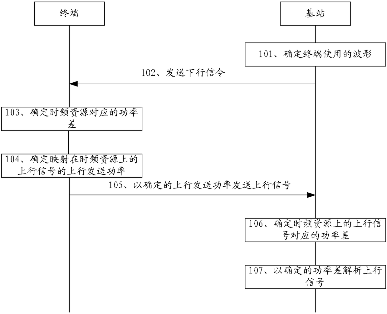
[0092] Such as figure 1 As shown, the uplink signal sending and receiving method provided by the embodiment of the present invention includes:

[0093] Step 101, the base station determines the waveform used by the terminal.

[0094] Step 102, the base station sends downlink signaling corresponding to the waveform to the terminal.

[0095] Step 103, the terminal determines the power difference corresponding to the target time-frequency resource.

[0096] Step 104, the terminal determines the uplink transmit power of the uplink signal mapped on the target time-frequency resource.

[0097] Step 105, the terminal transmits the uplink signal with the determined uplink transmission power.

[0098] Step 106, the base station determines the power difference corresponding to the uplink signal on the target time-frequency resource.

[0099] Step 107, the base station analyzes the uplink signal with the determined power difference.

[0100] Specifically, in the above step 101, the ...

Embodiment approach 1

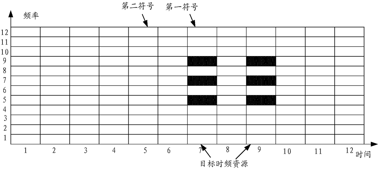
[0128] Embodiment 1. The power difference indicates the power difference between the first symbol and the second symbol

[0129] Such as figure 2 As shown, it is a schematic diagram of the target time-frequency resource provided by the embodiment of the present invention, wherein, figure 2 In , the target time-frequency resource refers to the OFDM symbol multiplexed by RS and channel, such as figure 2 As shown, both OFDM symbol 7 and OFDM symbol 9 are target time-frequency resources, wherein the RS mapped on the target time-frequency resource may be a reference signal for uplink channel sounding, for example, it may be a channel sounding reference signal (Sounding reference signal, SRS) or a reference signal for demodulation, for example, it may be a demodulation reference signal (Demodulation reference signal, DMRS), and the blank area on the target time-frequency resource is a channel for transmitting data, for example, it may be an uplink data channel ( Physical uplink...

Embodiment approach 2

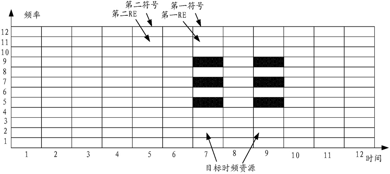
[0133] Embodiment 2: The power difference indicates the power difference between the first RE in the first symbol and the second RE in the second symbol

[0134] Such as image 3 As shown, it is a schematic diagram of another target time-frequency resource provided by the embodiment of the present invention, wherein, image 3 In , the target time-frequency resource refers to the time-frequency resource of the mapped channel on the OFDM symbol multiplexed by the RS and the channel, such as image 3 As shown, the white time-frequency resources (ie, white resource elements (Resource Element, RE)) on OFDM symbol 7 and OFDM symbol 9 are target time-frequency resources.

[0135] At this time, the power difference refers to the power difference between the REs on the first symbol and the REs on the second symbol, the first symbol is an OFDM symbol multiplexed with the RS and the channel, and the second symbol is an OFDM symbol not multiplexed with the RS.

[0136] That is, in Embod...


PUM


Abstract

The invention discloses a transmitting method and a receiving method for an uplink signal, a terminal and a base station. The transmitting method comprises the steps that: a terminal receives a downlink signaling issued by the base station, a waveform used by the terminal is determined according to the downlink signal, the terminal determines a power difference corresponding to a target time-frequency resource according to correlations between waveforms and power differences so as to determine the uplink transmission power of an uplink signal mapped on the target time-frequency resource according to the determined power difference, and the terminal transmits the uplink signal at the power, wherein the target time-frequency resource refers to either an OFDM symbol multiplexed by an RS and achannel or an RE of a mapping channel in the OFDM symbol multiplex by the RS and the channel. The embodiments, by reducing the transmission power of the uplink signal on the target time-frequency resource, achieve a reduced OFDM symbol multiplexed by the RS and the channel, thus allowing a power-limited terminal to transmit data normally and optimizing transmission power utilization of the power-limited terminal.

Description

technical field [0001] Embodiments of the present invention relate to the field of communication technologies, and in particular, to an uplink signal sending method, a receiving method, a terminal, and a base station. Background technique [0002] Currently, power control in Long Term Evolution (LTE) is mainly divided into physical uplink shared channel (physical uplink shared channel, PUSCH), physical uplink control channel (physical uplink control channel, PUCCH), physical random access Channel (Physical Random Access Channel, PRACH) and channel sounding reference signal (Sounding Reference Signal, SRS) power control. The basic principle is open loop plus closed loop. In the open loop, the terminal estimates the path loss Pathloss according to the downlink reference signal, and then performs uplink transmission power compensation; in the closed loop, the base station sends instructions to the terminal according to the uplink transmission power of the receiving terminal, in...

Claims


Application Information

Patent Timeline
Patent Type & Authority Applications(China)
IPC IPC(8): H04L27/26H04W72/04
CPCH04L27/2602H04W72/044H04W72/0473H04W72/20H04W52/146H04W52/262H04L27/2614H04L27/261H04L5/0007H04L5/0051H04L25/0226H04L27/2607H04W80/08
Inventor 赵兆秦龙纪刘榴
Owner HUAWEI TECH CO LTD
Why Eureka
Try Eureka