Measurement configuration method, device and system and network element

A technology for measuring configurations and network elements, applied in the field of communication

Active Publication Date: 2018-07-13
ZTE CORP
View PDF5 Cites 10 Cited by
  • Summary
  • Abstract
  • Description
  • Claims
  • Application Information

AI Technical Summary

Problems solved by technology

[0006] The technical problem to be solved by the present invention is to provide a measurement configuration method, device, network element and system to solve the problem of how to effectively coordinate the two serving base stations in the prior art so as to provide a reasonable RRC configuration for the UE

Method used


Image

  • Measurement configuration method, device and system and network element
  • Measurement configuration method, device and system and network element
  • Measurement configuration method, device and system and network element

Examples


specific Embodiment 1

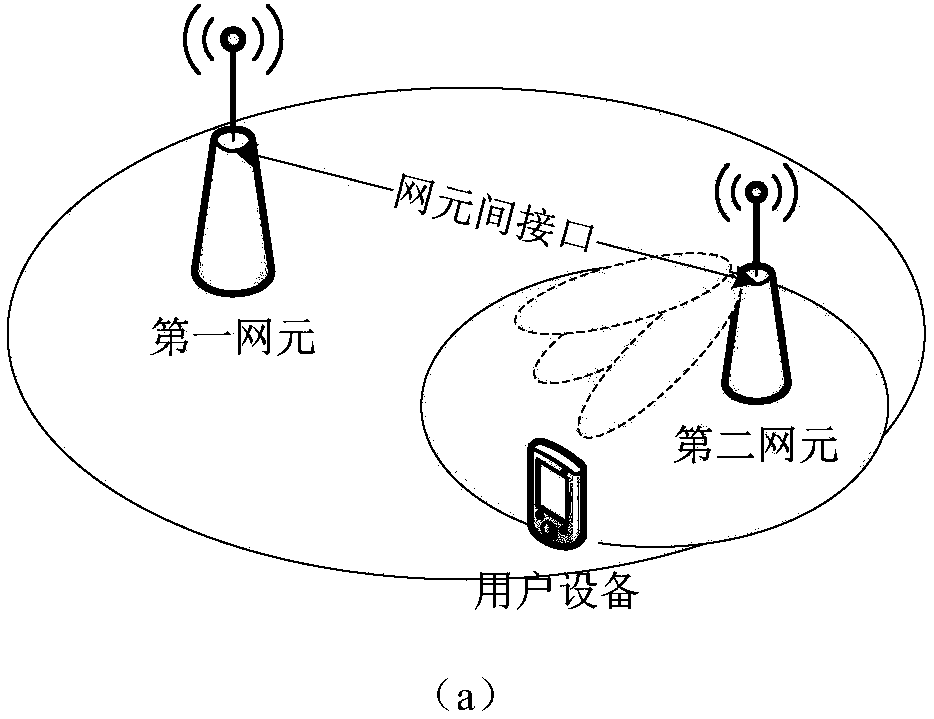
[0116] In the process of communicating with the UE, after the first network element makes an RRM decision to add the second network element, it notifies the second network element of the measurement result of the cell of the second network element, the first measurement configuration and the measurement parameters of the UE capability. If the second network element has new measurement requirements, such as obtaining beam measurement results, the second network element makes the second measurement configuration and feeds it back to the first network element. For the scenario, refer to figure 2 (a) Schematic. After receiving it, the first network element generates the control plane signaling and sends it to the UE through the wireless interface. Specific steps reference Figure 4 , and the relevant steps are described below.

[0117] Step 1: When the UE only accesses the first network element, user plane data and control plane signaling are transmitted between the UE, the fir...

specific Embodiment 2

[0125] refer to figure 2 The scenario in (b) shows that during the process of the first network element and the second network element communicating with the UE in a tightly coupled manner, the second network element has a new neighbor relationship, that is, the neighbor relationship of the third network element coverage, then the second network element can add a new measurement object for the UE, that is, modify the second measurement configuration. Specific steps reference Figure 5 , and the relevant steps are described below.

[0126] Step 1: During the communication between the second network element and the UE (that is, referring to the description of Embodiment 1, the second network element has received the first measurement configuration and UE capability measurement parameters notified by the first network element) , taking the following scenario as an example (not limited to the above scenario): the UE moves to the coverage of the third network element, or the thi...

specific Embodiment 3

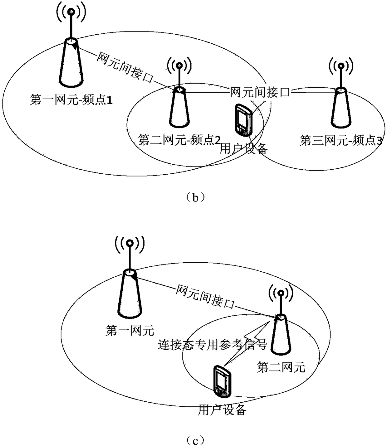
[0131] refer to figure 2 The scenario in (c) shows that in the process of the first network element and the second network element communicating with the UE in a tightly coupled manner, according to the characteristics of the second RAT, the second network element may need to provide additional measurement references for the UE signal, therefore, a second measurement configuration needs to be performed on the UE. Similar to Embodiment 2, this embodiment still adopts an architecture in which the first network element and the second network element can respectively transmit control plane signaling with the UE. Specific steps reference Image 6 , and the relevant steps are described below.

[0132] Step 1: After the UE accesses the second network element (similar to the description in Embodiment 2, the second network element has received the first measurement configuration and UE capability measurement parameters notified by the first network element), according to the second ...


PUM


Abstract

The invention discloses a measurement configuration method, device and system and a network element, relates to the technical field of communication and is used for solving the problem of how to carryout effective coordination on two service eNBs, thereby providing reasonable RRC (Radio Resource Control) configuration for UE in the prior art. The method comprises the steps that a first network element carries out first measurement configuration on the user equipment; the first network element sends the first measurement configuration to a second network element; the first network element carries out coordination configuration on the second network element, so the second network element carries out second measurement configuration on the user equipment, wherein a control plane interface exists between the first network element and a core network, the control plane interface does not exist between the second network element and the core network, and different radio access technologies are employed on radio interfaces of the first network element and the second network element; and the first network element and the second network element provide radio resources for the user equipment, wherein the radio resources are at least used for data transmission of a user plane.

Description

technical field [0001] The present invention relates to the field of communication technology, in particular to a measurement configuration method, device, network element and system. Background technique [0002] In order to realize efficient and reliable radio resource management (Radio Resource Management, RRM), in the fourth generation (the fourth Generation, 4G) communication system, use long term evolution (Long Term Evolution, LTE) radio access technology (Radio Access Technology , the evolved base station (E-UTRAN NodeB, eNB) of the RAT) will provide the UE with measurement configurations, wherein the measurement configurations include the following parameters: measurement objects, reporting configurations, measurement identifiers, quantity configurations, and measurement intervals. The UE performs measurement according to the measurement configuration and reports the cell-level measurement result to the eNB. [0003] In the dual connectivity (Dual Connectivity, DC)...

Claims


Application Information

Patent Timeline
Patent Type & Authority Applications(China)
IPC IPC(8): H04W24/02H04W28/02H04W28/08H04W48/14H04W72/04H04W72/12
CPCH04W24/02H04W28/0205H04W48/14H04W72/1215H04W72/52H04W72/51H04W24/10H04W28/02H04W36/28H04W72/04H04W72/12
Inventor 王昕施小娟
Owner ZTE CORP
Why Eureka
Try Eureka