Constant-resistance pneumatic box

A force pneumatic box and resistance technology, applied in the field of constant resistance pneumatic box, can solve problems affecting training effect, impact injury of joints and connective tissue, etc., and achieve the effect of high compensation precision and simple structure

Pending Publication Date: 2018-07-17
NANTONG IRONMASTER SPROTING IND
View PDF5 Cites 2 Cited by
  • Summary
  • Abstract
  • Description
  • Claims
  • Application Information

AI Technical Summary

Problems solved by technology

This change in resistance is detrimental when training, not only does it affect train

Method used


Image

  • Constant-resistance pneumatic box
  • Constant-resistance pneumatic box
  • Constant-resistance pneumatic box

Examples


Embodiment Construction

[0028] It should be noted that components in the various figures may be shown exaggerated for the purpose of illustration and are not necessarily true to scale. In the various figures, identical or functionally identical components are assigned the same reference symbols.

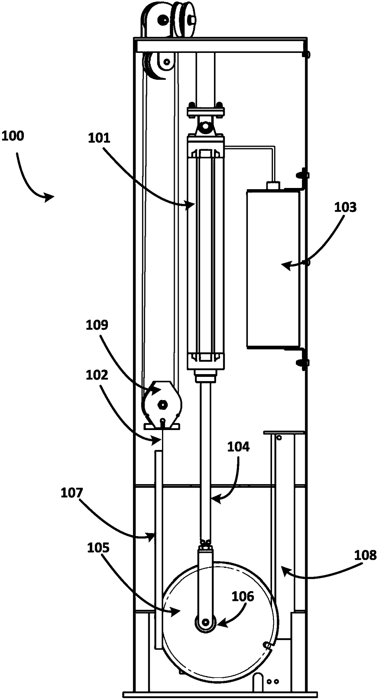
[0029] figure 1 A schematic diagram of a constant resistance aerodynamic box 100 according to the present invention is shown.

[0030] Such as figure 1 As shown, the constant resistance pneumatic box 100 includes an air cylinder 101 . The cylinder 101 includes a piston (not shown) and a piston rod 104, wherein the cylinder 100 is fixed so that it can rotate at a certain angle (such as 30°, 45° or 90°). exist figure 1 In , the cylinder 101 is shown with one end fixed to the housing by a rotating shaft so that it can rotate. However, other rotational attachments are also conceivable, for example the cylinder is attached rotatably in its middle to the housing. One end of the piston rod 104 is connected ...


PUM


Abstract

The invention relates to a constant-resistance pneumatic box. The constant-resistance pneumatic box comprises an air cylinder, a gas storage tank, two guide rails, a pull rope and an eccentric wheel,wherein the air cylinder comprises a piston and a piston rod, the air cylinder is fixed in the manner of being capable of rotating by a certain angle in the plane of the length direction of the air cylinder, one end of the piston rod is connected with the piston, and the other end of the piston rod is connected with the eccentric wheel; the gas storage tank is used for storing compressed gas and connected with the air cylinder to supply compressed gas to the air cylinder; the two guide rails are used for guiding the eccentric wheel; the pull rope is used for transmitting the pull force of a user to the eccentric wheel; the pull rope is wound around the eccentric wheel on the side away from the air cylinder, the eccentric wheel is arranged between the two guide rails so that the eccentric wheel can slide in the two guide rails under the pull of the pull rope, and the piston rod is connected to the non-central position of the eccentric wheel, so that the angle between the piston rod andthe pull rope becomes large in the sliding process of the eccentric wheel. Through the pneumatic box, constant resistance output can be achieved.

Description

technical field [0001] The present invention generally relates to the field of fitness equipment, in particular to a constant resistance pneumatic box. Background technique [0002] With the popularization of health knowledge and the improvement of people's living standards, people pay more and more attention to their own health. Fitness is increasingly popular as a way to stay healthy. Resistance training is a common form of fitness exercise used to improve cardiorespiratory fitness, get in shape, or perform professional conditioning. Conventional resistance training equipment generally changes resistance by replacing or adding bell plates or selector plates. However, the resistance of these machines changes as the exerciser moves. For example, when doing a centripetal movement (muscle contraction at this time), the resistance often becomes smaller due to the inertial effect of the selection piece itself. This change in resistance is detrimental when training, not only ...

Claims


Application Information

Patent Timeline
IPC IPC(8): A63B21/008A63B24/00
CPCA63B21/008A63B24/0087
Inventor 康烨张志均蔡培培康海纯邢英成孙锋磊王佳玲
Owner NANTONG IRONMASTER SPROTING IND
Why Eureka
Try Eureka