Clamping clamp for circumferential uniform machining of grooves in cam surface of swing sliding base

A technology with uniform circumferential distribution and cam surface, applied in the direction of manufacturing tools, metal processing equipment, metal processing machinery parts, etc., can solve the problems of affecting processing accuracy, low processing efficiency, error accumulation, etc., to avoid repeated positioning and improve processing efficiency Effect

Pending Publication Date: 2018-07-17
JIANGSU RUIDE MACHINERY CO LTD
View PDF6 Cites 4 Cited by
  • Summary
  • Abstract
  • Description
  • Claims
  • Application Information

AI Technical Summary

Problems solved by technology

[0002] The shape of the swing slide is extremely complex (such as figure 1 ), when the milling machine is processing the groove 100 to be processed on the cam surface 14 in the swing slide, it adopts a step-by-step processing method, so it needs to clamp the part multiple times, so the processing efficiency is low, and at the same time due to Multiple clamping and inconsistent positioning surfaces lead to error accumulation and affect the improvement of machining accuracy

Method used


Image

  • Clamping clamp for circumferential uniform machining of grooves in cam surface of swing sliding base
  • Clamping clamp for circumferential uniform machining of grooves in cam surface of swing sliding base
  • Clamping clamp for circumferential uniform machining of grooves in cam surface of swing sliding base

Examples


Embodiment Construction

[0022] The present invention will be further described below in conjunction with the accompanying drawings.

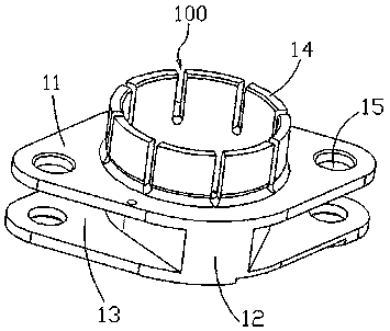
[0023] Such as Figure 2 to Figure 7 , the present invention is a clamping fixture with evenly distributed grooves on the cam surface of the oscillating slide. The oscillating slide includes two connecting pieces 11 arranged in parallel on the upper and lower sides. A slot 13 is formed between the two connecting pieces 11. A connecting block 12 is arranged in the card slot 13 , and the connecting block 12 is integrally formed with the two connecting pieces 11 . A cam surface 14 is provided on the upper end surface of the upper connection piece 11 , and a connection hole 15 is provided at both ends of each connection piece 11 .

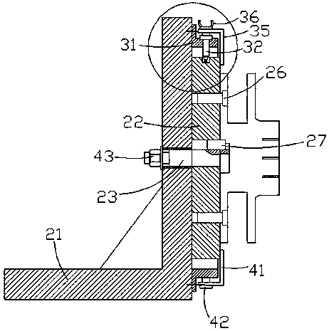
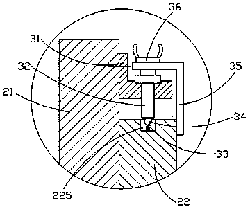
[0024] The fixture of the present invention for clamping the swing slide includes a seat body 21, a turntable 22, a rotating shaft 23, a positioning nail 26, a key 27, a fastening screw 28, a pressure plate 29, a reference seat 31, a reference...


PUM


Abstract

The invention discloses a clamping clamp for the circumferential uniform machining of grooves in the cam surface of a swing sliding base. A rotating shaft is connected to a seat body in a rotating manner, the rotating shaft is connected with a turn plate through a key, and two locating holes are arranged in the turn plate. Locating nails penetrate through connecting holes in a lower connecting plate and extend into the locating holes. A pressing plate is fixed to the turn plate through a fastening screw, the fastening screw is tightened, and the pressing plate is pressed on the lower connecting plate. A reference base is fixedly connected to the seat body, and the reference base is located at the outer side of the turn plate and coaxially arranged with the turn plate. An even number of reference nails are inserted to the circumferential wall of the reference base, steel balls are connected to the circumferential wall of the turn plate through the elastic support of springs, and the steel balls are pressed against the reference nails. A fixed plate is fixedly connected to the turn plate, butterfly screws are connected to the fixed plate through threads, and the bottom ends of the butterfly screws are pressed against the reference nails against which the steel balls are pressed. The clamping number is low, the repeated locating of the swing sliding base is avoided, and the machining efficiency is greatly increased.

Description

Technical field: [0001] The invention relates to a clamping fixture which is machined with evenly distributed grooves on the cam surface of an oscillating sliding seat. Background technique: [0002] The shape of the swing slide is extremely complex (such as figure 1 ), when the milling machine is processing the groove 100 to be processed on the cam surface 14 in the swing slide, it adopts a step-by-step processing method, so it needs to clamp the part multiple times, so the processing efficiency is low, and at the same time due to Multiple clamping and inconsistent positioning surfaces lead to error accumulation and affect the improvement of machining accuracy. Invention content: [0003] In order to solve the above-mentioned problems in the prior art, the present invention provides a clamping fixture in which grooves are uniformly distributed in the circumferential direction of the cam surface of the swing slide seat. [0004] The technical solution adopted in the ...

Claims


Application Information

Patent Timeline
Patent Type & Authority Applications(China)
IPC IPC(8): B23Q3/06B23C3/28
CPCB23C3/28B23Q3/06
Inventor 宋玻李金华宋文杰嵇太国孙忠
Owner JIANGSU RUIDE MACHINERY CO LTD
Why Eureka
Try Eureka