Form and position measurement flexible clamp and form and position measurement method for columnar part

A technology of flexible fixtures and parts, applied in the field of shape and position measurement fixtures, can solve the problems of unusable clamping and failure to ensure the shape and position of parts, etc., and achieve the effect of improving clamping efficiency, increasing contact surface, and ensuring no occlusion

Pending Publication Date: 2022-07-12
CHANGSHU INSTITUTE OF TECHNOLOGY
View PDF5 Cites 1 Cited by
  • Summary
  • Abstract
  • Description
  • Claims
  • Application Information

AI Technical Summary

Problems solved by technology

The fixture is specially designed for measuring the shape characteristics of the specific detection object, and cannot be used for other parts clamping
[0005] To sum up, there is currently no universal fixture for cylindrical parts with different cross-sections and different sizes under the condition that the part shape and position detection is not blocked.

Method used


Image

  • Form and position measurement flexible clamp and form and position measurement method for columnar part
  • Form and position measurement flexible clamp and form and position measurement method for columnar part
  • Form and position measurement flexible clamp and form and position measurement method for columnar part

Examples


Embodiment 1

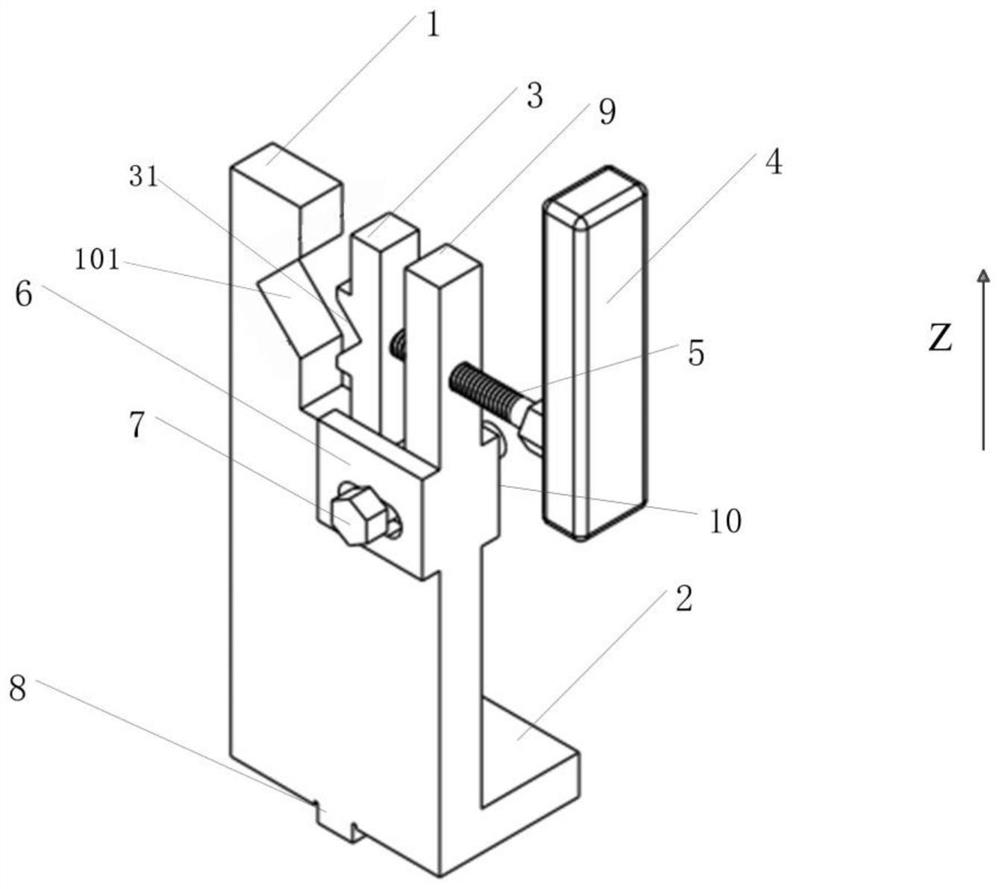
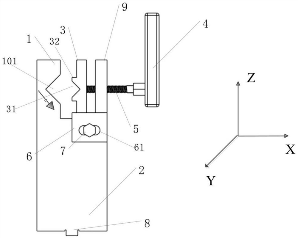
[0034] like figure 1 , 2 As shown in the figure, a flexible fixture for measuring the shape and position of a columnar part includes a fixed base 2, and at least one pair of splints is arranged on the fixed base 2. The pair of splints includes a fixed splint 1 and a corresponding movable splint 3. The fixed splint 1 A first V-shaped groove 101 is provided, and the movable splint 3 is provided with a second V-shaped groove 31 opposite to the first V-shaped groove 101 . The movable splint 3 is connected to a propulsion mechanism, and the propulsion mechanism drives the movable splint 3 to move. The clamping method is a unilateral movable adjustment method, that is, the fixed splint 1 is fixed on the fixed seat 2 as a fixed end, and the movable splint 3 can be adjusted according to the section size of the columnar part. The double-sided movable clamping can reduce the repeated positioning of precision measuring equipment and improve the clamping efficiency.

[0035] In a prefer...

Embodiment 3

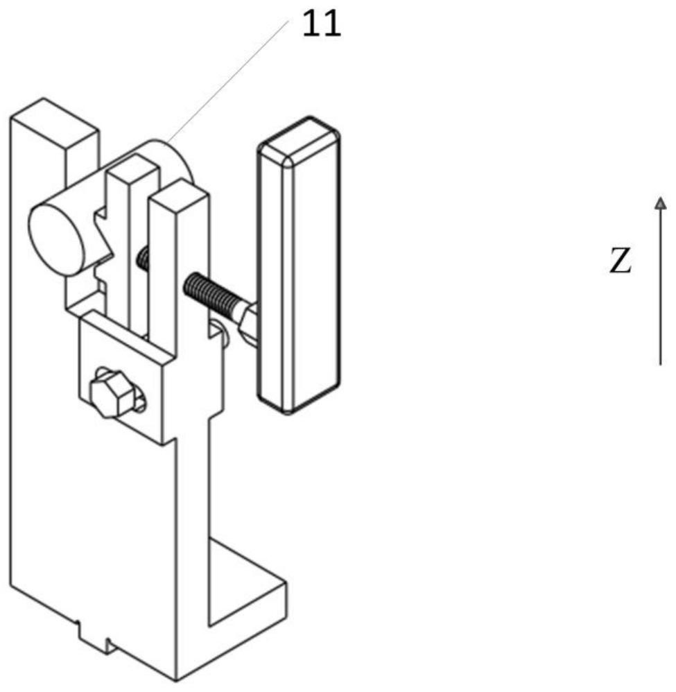
[0049] Specifically, when the part to be measured 11 needs to be fixed, firstly, the part is matched with the groove of the fixed splint 1 to constrain the degree of freedom of rotation and movement of the part to be measured 11 along the X axis; at the same time, the handle 24 is rotated to fix it on The No. 1 screw 5 on the handle 24 passes through the thread of the fixed push block 9, and pushes the movable splint 2 to move along the track between the limit block 6 and the limit block 10 until the part 11 is fixed and clamped, which further constrains the part to be tested 11 Degree of freedom of rotation and movement along the Y axis; at this time, the part to be tested 11 is in contact with the fixture on all four sides, that is, the upper surface, the lower surface of the fixed splint 1, the upper surface (or upper side) and the lower surface of the movable splint 3 (or the lower side) is in contact with the cylindrical part 11 to be measured, the movement degree of freed...


PUM


Abstract

The invention discloses a shape and position measurement flexible clamp for a columnar part, which comprises a fixed seat, at least one clamping plate pair is arranged on the fixed seat, the clamping plate pair comprises a fixed clamping plate and a movable clamping plate corresponding to the fixed clamping plate, the fixed clamping plate is provided with a first V-shaped groove, and the movable clamping plate is provided with a second V-shaped groove. The movable clamping plate is provided with a second V-shaped groove opposite to the first V-shaped groove, the movable clamping plate is connected with a propelling mechanism, and the propelling mechanism drives the movable clamping plate to move. The clamp is simple in structure, does not damage precise parts, can completely detect various form and position errors, has universality when the same type of parts are measured and the size of a detected object has deviation, and can reduce clamp disassembly and unnecessary repeated positioning, thereby reducing the labor intensity of workers and improving the measurement efficiency.

Description

technical field [0001] The invention belongs to the technical field of shape and position measurement fixtures, and relates to a shape and position measurement flexible fixture for cylindrical parts and a shape and position measurement method. Background technique [0002] There are shape and position errors after machining high-precision parts. It is necessary to process the dimensional accuracy (such as length, diameter, angle, etc.), shape accuracy (straightness, roundness, contour, etc.), position accuracy (parallelism, etc.) of precision parts according to the accuracy requirements. (degree, perpendicularity, coaxiality, etc.) Before measuring the workpiece, it is necessary to use a fixture to fix the workpiece. Different from parts processing and clamping, the design of the clamping fixture required for measurement needs to fully consider the integrity of the detection area. When testing the same type of high-precision parts in batches, the clamping simplicity of the ...

Claims


Application Information

Patent Timeline
Patent Type & Authority Applications(China)
IPC IPC(8): B25B11/00G01B21/00G01B21/20
CPCB25B11/00G01B21/00G01B21/20
Inventor 丁卫杨洋周建鹏朱培逸
Owner CHANGSHU INSTITUTE OF TECHNOLOGY
Why Eureka
Try Eureka