Method for preparing liquid by low-temperature rectification

A low-temperature rectification and rectification technology, which is applied in refrigeration, liquefaction, liquefaction, solidification, etc., can solve the problems of high working pressure, difficult operation, and increased floor space of equipment

Inactive Publication Date: 2018-07-17
HANGZHOU FORTUNE CRYOGENIC EQUIP CO LTD
View PDF0 Cites 7 Cited by
  • Summary
  • Abstract
  • Description
  • Claims
  • Application Information

AI Technical Summary

Problems solved by technology

On the one hand, this situation virtually increases the investment cost of the equipment and increases the floor area. Another important shortcoming is that the working pressure of the equipment is high and it is not easy to operate.

Method used


Image

  • Method for preparing liquid by low-temperature rectification

Examples


Embodiment 1

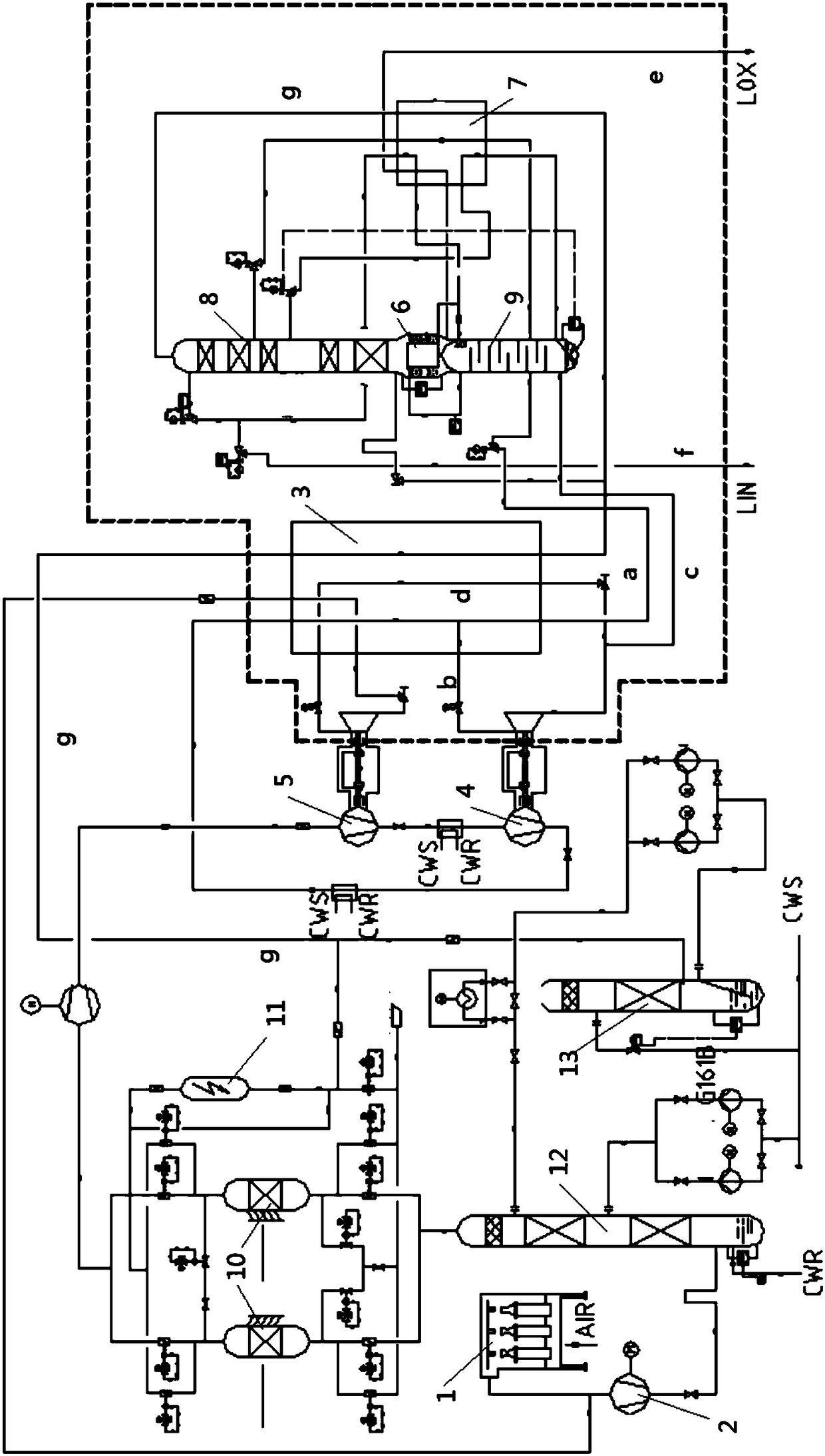
[0015] Such as figure 1 The shown device for obtaining liquid by low temperature rectification includes a filter 1, an air compressor 2, a precooling system, a purification system and a cold box. The cold box includes a box body, a heat exchanger 3 and a rectification system inside the box body, and a low-temperature expander 4 and a high-temperature expander 5 connected outside the box body. The filter 1, the air compressor 2, the pre-cooling system and the purification system are connected in sequence, and the pipelines from the purification system are introduced into the heat exchanger 3 after passing through the high-temperature expander 5 and the low-temperature expander 4 in turn, and the heat exchanger 3 The pipeline is divided into two paths, and the first pipeline a is led out from the end of the heat exchanger 3 and then introduced into the rectification system. The second pipeline b is drawn from the middle of the heat exchanger 3 and passes through the low-tempera...

Embodiment 2

[0020] This embodiment is based on the device for obtaining liquid by low-temperature rectification in Example 1, and the method for obtaining liquid by low-temperature rectification includes the following steps:

[0021] Step 1: The raw air passes through the air filter to remove dust and mechanical impurities, enters the raw air compressor to pressurize, then passes through the air pre-cooling system to cool down, and then enters the air purification system to remove H2O, CO2, C2H2, etc. in the raw air pure matter.

[0022] Step 2: The purified air continuously enters the booster end of the high-temperature expander and the low-temperature expander for pressurization, and then enters the heat exchanger after being cooled by the cooler at the booster end. The air in the heat exchanger is divided into two streams; the first stream The air is condensed into liquid air through the heat exchanger, and after being drawn out, it is throttled and directly enters the lower rectificat...


PUM


Abstract

The invention relates to a method for preparing liquid by low-temperature rectification. The method comprises the steps that 1, raw material air passes through an air compressor, an air pre-cooling system and an air purification system; 2, the purified air enters the heat exchanger continuously, and air in the heat exchanger is divided into two strands, the first strand of air passes through the heat exchanger to be condensed into liquid to enter a rectifying lower tower, the second strand of air is pumped out and then enters a low-temperature expansion machine for expansion, part of the air enters the rectifying lower tower, and the other part of the air is returned to the air compressor inlet or the air pre-cooling system after being subjected to repeated thermal expansion by the heat exchanger; 3, liquefied air after throttling which flows into the lower tower and the expanded part of air into the rectifying lower tower for rectification, so as to obtain a liquid nitrogen product;and rectifying is carried out again through a rectifying upper tower to obtain the liquid oxygen product. According to the method, the exhaust pressure of the circulating air compressor is effectivelyreduced, the unit refrigerating capacity of the expansion machine is improved, and the purposes of enabling the equipment to be easy to operate and reducing the primary investment of the equipment are achieved.

Description

technical field [0001] The invention relates to a method for producing liquid by low-temperature rectification. Background technique [0002] At present, the demand for liquid air separation products is still greater, but when the liquid volume is large and the variety requirements are large, the number of moving equipment involved in the air separation system and the working pressure will be relatively high. Conventional process for producing a large amount of liquid products: the raw gas air compressor is compressed and boosted to 0.62MPaA by three stages, and then enters the pre-cooling and purification system to remove impurities. Except part of the purified air is used as instrument air for the air separation unit, the rest All enter the circulating air compressor to pressurize. After the supercharged air is finally cooled, part of it is pumped into the high-pressure main exchanger for cooling, then goes to the high-temperature expander for expansion, reheats and retur...

Claims


Application Information

Patent Timeline
Patent Type & Authority Applications(China)
IPC IPC(8): F25J3/04
CPCF25J3/0403F25J3/04157F25J3/04187F25J3/04624F25J3/04775F25J3/04781F25J3/04345F25J3/04393F25J3/04412F25J2205/32F25J2205/34F25J2245/50
Inventor 孙世学储波阮家林
Owner HANGZHOU FORTUNE CRYOGENIC EQUIP CO LTD
Why Eureka
Try Eureka