Ground-in-hole combined detecting system based on time domain electromagnetic method and application method thereof

A time-domain electromagnetic and detection system technology, which is applied in the field of engineering geophysical exploration, can solve the problems of strong mutual inductance of detection devices, difficulty in realizing the periphery of drilling holes, and poor signal-to-noise ratio of measurement signals, so as to improve detection resolution and positioning accuracy, and highlight Abnormal response characteristics, the effect of reducing the influence of the background field

Active Publication Date: 2018-07-17
安徽晟北辰地质勘测设计有限公司
View PDF9 Cites 6 Cited by
  • Summary
  • Abstract
  • Description
  • Claims
  • Application Information

AI Technical Summary

Problems solved by technology

[0004] The technical problems to be solved by the present invention are: the strong mutual inductance of detection devices in the conventional time-domain electromagnetic method causes serious primary field interference, prominent human interference during ground detection, poor signal-to-noise ratio of measurement signals, and inaccurate depth positioning and vertical resolution. Factors such as poor effect greatly affect the detection accuracy, and it is difficult to achieve the effect of fine exploration in three-dimensional space around the borehole

Method used


Image

  • Ground-in-hole combined detecting system based on time domain electromagnetic method and application method thereof
  • Ground-in-hole combined detecting system based on time domain electromagnetic method and application method thereof
  • Ground-in-hole combined detecting system based on time domain electromagnetic method and application method thereof

Examples


Embodiment Construction

[0053] In order to facilitate those skilled in the art to understand the technical solution of the present invention, the technical solution of the present invention will be further described in conjunction with the accompanying drawings.

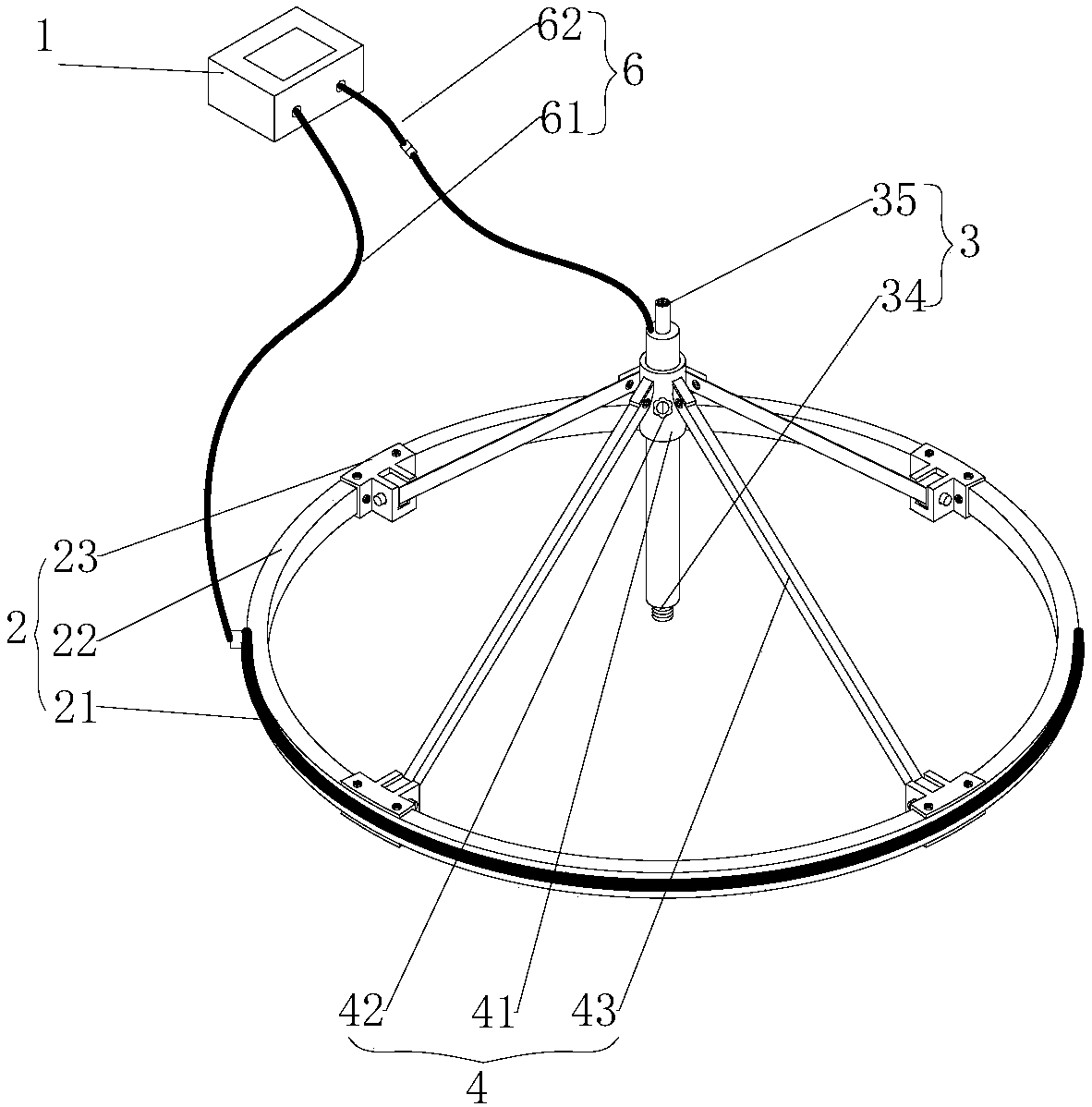
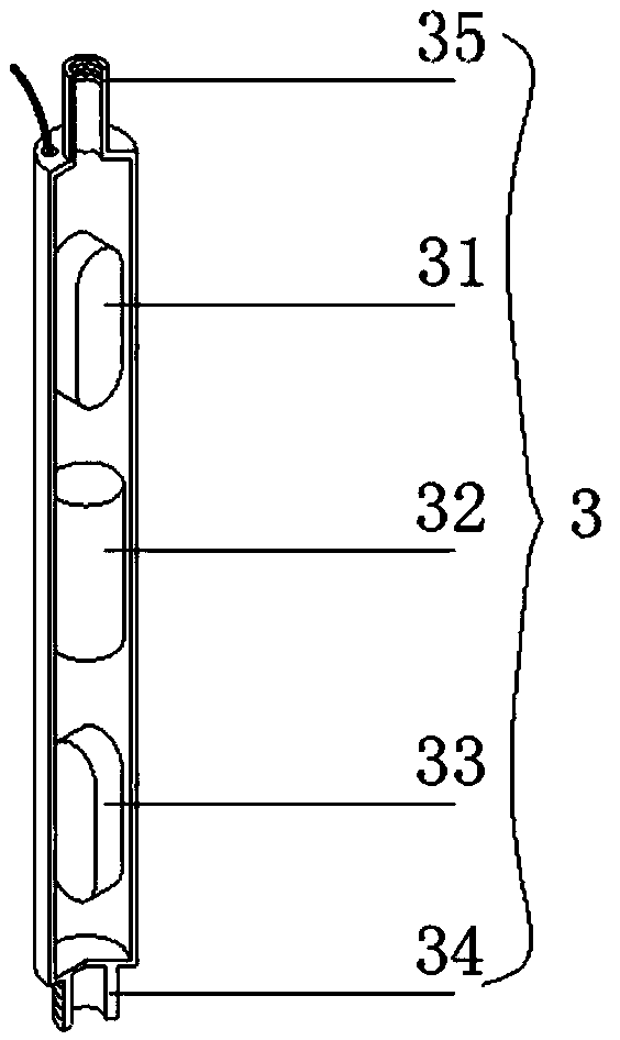
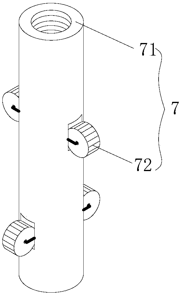
[0054] Such as Figure 1 to Figure 9 As shown, the embodiment of the present invention provides a ground-hole joint detection system based on time-domain electromagnetic method and its application method. The detection system includes an electromagnetic instrument 1, a sending device 2, a rod receiving device 3, and a sending-receiving fixed frame 4. The push rod 5 and the wall-mounted anti-rotation device 7, the electromagnetic instrument 1 is connected with the sending device 2 and the rod-shaped receiving device 3 through the connecting wire 6; the sending device 2 and the rod-shaped receiving device 3 are connected by the sending-receiving fixed frame Assembled and connected as a whole for ground detection, the push rod 5 is used to sen...


PUM


Abstract

The invention discloses a ground-in-hole combined detecting system which comprises an electromagnetic instrument, a transmitting device, a rod-shaped receiving device, a transmitting-receiving fixingframe, a wall abutting type rotation preventer and a pushing rod. The electromagnetic instrument supports sequential intelligent starting and stoppage of single or a plurality of transmitting devicesand a plurality of receiving channels. A transmitting coil in the transmitting device is arranged on an annular frame. The upper end and the lower end of the rod-shaped receiving device are respectively provided with a pushing rod joint and a rotation preventer joint. In ground detection, the rod-shaped receiving device is arranged in the sleeve of a transmitting-receiving fixing frame. In in-holedetection, the rod-shaped receiving device is connected with the wall abutting type rotation preventer and performs in-hole movement by means of the pushing rod. An application method based on the detecting system of the invention mainly comprises ground and in-hole detection. According to a ground field source excitation characteristic, the application method can be divided into a fixed-source excitation mode, a movable-source excitation mode and a multi-source successive excitation mode, and single-hole or multiple-hole receiving. The ground-in-hole combined detecting system and the application method have advantages of reducing one-time field interference and humanistic electromagnetic interference, realizing high signal-to-noise ratio, improving detecting precision and realizing three-dimensional space detection to periphery of a drilling hole.

Description

technical field [0001] The invention belongs to the field of engineering geophysical prospecting, and in particular relates to a ground-in-hole joint detection system and an application method based on a time-domain electromagnetic method. Background technique [0002] Geophysical prospecting methods are economical and efficient, and have been widely used in many fields such as geological survey, resource exploration and development, and geological safety. With the rapid development of domestic infrastructure, the demand for underground exploration has become increasingly prominent, such as transportation, water conservancy, industrial and civil construction, etc. Engineering geology and hydrogeological surveys involved in civil engineering, especially the fine exploration of unfavorable geological bodies, underground pipelines, underground obstacles, etc., have gradually become application hotspots. At present, the conventional geophysical prospecting methods mainly include...

Claims


Application Information

Patent Timeline
Patent Type & Authority Applications(China)
IPC IPC(8): G01V3/08G01V3/10G01V3/26G01V3/28
CPCG01V3/08G01V3/10G01V3/26G01V3/28Y02A90/30
Inventor 倪子涵计成富陈陆望孙尚云赵萍曹爽余睿泽张闪闪翟福勤
Owner 安徽晟北辰地质勘测设计有限公司
Why Eureka
Try Eureka