Head radiofrequency coil for magnetic resonance imaging system

A magnetic resonance imaging and radio frequency coil technology, applied in magnetic resonance measurement and other directions, can solve the problems of affecting imaging clarity, increasing use cost, and insufficient Q value, and achieving the effects of enhancing signal receiving performance, reducing loss, and improving thermal insulation effect.

Active Publication Date: 2013-05-22
TIME MEDICAL JIANGSU
View PDF4 Cites 7 Cited by
  • Summary
  • Abstract
  • Description
  • Claims
  • Application Information

AI Technical Summary

Problems solved by technology

[0004] The existing method is to improve the wiring to reduce the coupling capacitance of the overlapping parts of the coil, thereby increasing the Q value of the coil, but due to the limitation of the inherent resistance of the copper conductor at room temperature, the Q value is still not high enough, and the figure associated with the electronic thermal noise Image noise affects the imaging clarity. The conductor used is a normal temperature copper conductor. During the imaging process, in order to reduce the influence of the thermal noise and inherent resistance of the copper conductor in the copper conductor, the signal-to-noise ratio must be increased by extending the scan time, resulting in equipment The increase of the cost of use; the current commonly used coil design is mainly based on the normal temperature conductor, and generally cannot obtain a high no-load Q

Method used


Image

  • Head radiofrequency coil for magnetic resonance imaging system
  • Head radiofrequency coil for magnetic resonance imaging system
  • Head radiofrequency coil for magnetic resonance imaging system

Examples


Embodiment 1

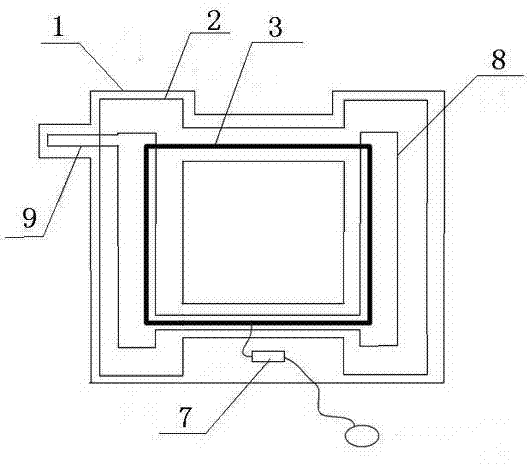
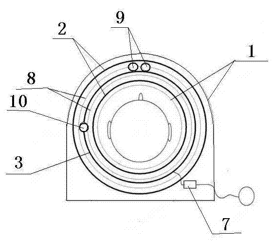
[0026] Such as Figure 1A , Figure 1B and Figure 2A As shown, a head radio frequency coil for a magnetic resonance imaging system, the radio frequency coil includes a coil housing 1, a vacuum cover 2, a liquid nitrogen device, a coil conductor 3 and a low-noise preamplifier 7, the radio frequency coil is a radio frequency The receiving coil is in the receiving mode when it works, and another transmitting coil that comes with the MRI system is needed to excite the object under test, and then the receiving coil receives the signal generated by the object under test.

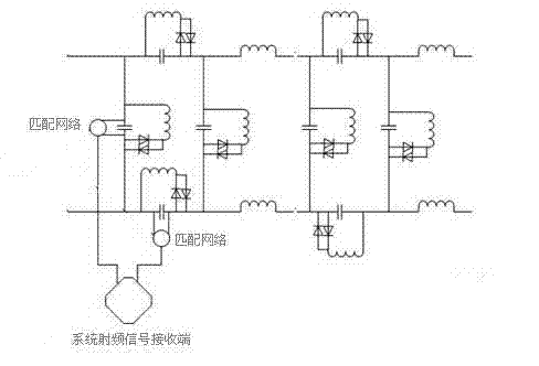
[0027] Such as Figure 3A , Figure 3B and Figure 3C As shown, the coil conductor 3 is composed of an end ring 4, an even number of legs 5 parallel to each other connected to both ends of the end ring, and a resonant capacitor 6. The resonant capacitor 6 can be welded on the end ring 4 or each leg 5 to achieve the resonance condition. There are different voltage differences at the two ends of the resonant ca...

Embodiment 2

[0042] Such as Figure 1A , Figure 1B and Figure 2B As shown, a head radio frequency coil for a magnetic resonance imaging system, the radio frequency coil includes a coil housing 1, a vacuum cover 2, a liquid nitrogen device, a coil conductor 3 and a low-noise preamplifier 7, when used as a receiving / transmitting coil , the excitation and reception coils are the same coil.

[0043] First, connect the external vacuum device to the pumping port 10 on the vacuum cover 2 and pump the vacuum to make the space between the vacuum cover 2 and the liquid nitrogen tank 8 reach a certain degree of vacuum, then seal the pumping port 10 and disconnect the vacuum pump. Install shell 1.

[0044] Then liquid nitrogen is added to the liquid nitrogen tank 8 through the liquid nitrogen filling pipe 9, so that the coil 3 in contact with it is cooled to the liquid nitrogen temperature, and the temperature of the liquid nitrogen tank 8 will drop to 77K.

[0045] Place the entire refrigeration...


PUM


Abstract

The invention discloses a head radiofrequency coil for a magnetic resonance imaging system. The radiofrequency coil comprises a coil shell (1), a vacuum shield (2), a liquid nitrogen apparatus and a coil conductor (3). The radiofrequency coil is a radiofrequency receiving coil or an operable radiofrequency coil capable of both transmitting and receiving. The coil conductor (3) consists of end rings (4), legs (5) in even number and resonant capacitors (6), wherein the legs (5) parallel one another are connected to two ends of the end rings (4), and the resonant capacitors (6) are connected with the coil conductor (3). The coil conductor (3) of different structure can be selected according to different direction of a main magnetic field. The liquid nitrogen apparatus is arranged on the coil conductor (3) and refrigerates a coil through liquid nitrogen. The coil conductor can be used as the receiving coil or the receiving/transmitting coil, has good orthogonal receiving and excitation performance and has high uniformity in imaging areas. Since the conductor is cooled by the liquid nitrogen, loss caused in the magnetic resonance receiving process and thermal noise generated due to resistance can be reduced and the signal-to-noise ratio of acquired images is increased.

Description

technical field [0001] The invention relates to a head radio frequency coil for a magnetic resonance imaging system, in particular to a radio frequency coil which adopts liquid nitrogen refrigeration and uses coil conductors with receiving or transmitting / receiving to diagnose the head. Background technique [0002] At present, magnetic resonance imaging technology has been widely used in various large medical institutions in the world and has achieved huge and unique benefits in medical practice. These magnetic resonance imaging techniques not only have medical diagnostic value in identifying and evaluating pathology and judging the health status of the tested tissue, but also are widely used in clinical and research; although through unremitting efforts, magnetic resonance imaging has made great progress, but There is still a need for further improvements in magnetic resonance imaging, such as higher contrast, enhanced signal-to-noise ratio, faster acquisition speed, and / o...

Claims


Application Information

Patent Timeline
Patent Type & Authority Applications(China)
IPC IPC(8): G01R33/36
Inventor 刘尊钢徐光福胡长伍钱茂飞徐臻峰高而震马启元
Owner TIME MEDICAL JIANGSU
Why Eureka
Try Eureka