Visual identification-based precise shaft size measurement method, apparatus and system

A technology of visual recognition and measurement method, which is applied in the direction of measuring device, optical device, image data processing, etc., can solve the problems of low measurement efficiency and unable to meet real-time requirements, and achieve both overall image and high measurement accuracy, and noise insensitivity , fast processing effect

Active Publication Date: 2018-07-17
EAST CHINA JIAOTONG UNIVERSITY
View PDF5 Cites 15 Cited by
  • Summary
  • Abstract
  • Description
  • Claims
  • Application Information

AI Technical Summary

Problems solved by technology

[0005] The purpose of the present invention is to provide a precision shaft size measurement method, device and system based on visual recognition, so as to solve the technical problem that the measurement efficiency of the slender shaft measurement scheme based on machine vision is low and cannot meet the real-time requirements in the prior art

Method used


Image

  • Visual identification-based precise shaft size measurement method, apparatus and system
  • Visual identification-based precise shaft size measurement method, apparatus and system

Examples


Embodiment Construction

[0051] The following will clearly and completely describe the technical solutions in the embodiments of the present invention with reference to the accompanying drawings in the embodiments of the present invention. Obviously, the described embodiments are only some, not all, embodiments of the present invention. Based on the embodiments of the present invention, all other embodiments obtained by persons of ordinary skill in the art without making creative efforts belong to the protection scope of the present invention.

[0052] In order to make the technical solution of the present invention more obvious and understandable, the present invention will be further described in detail below in conjunction with specific embodiments.

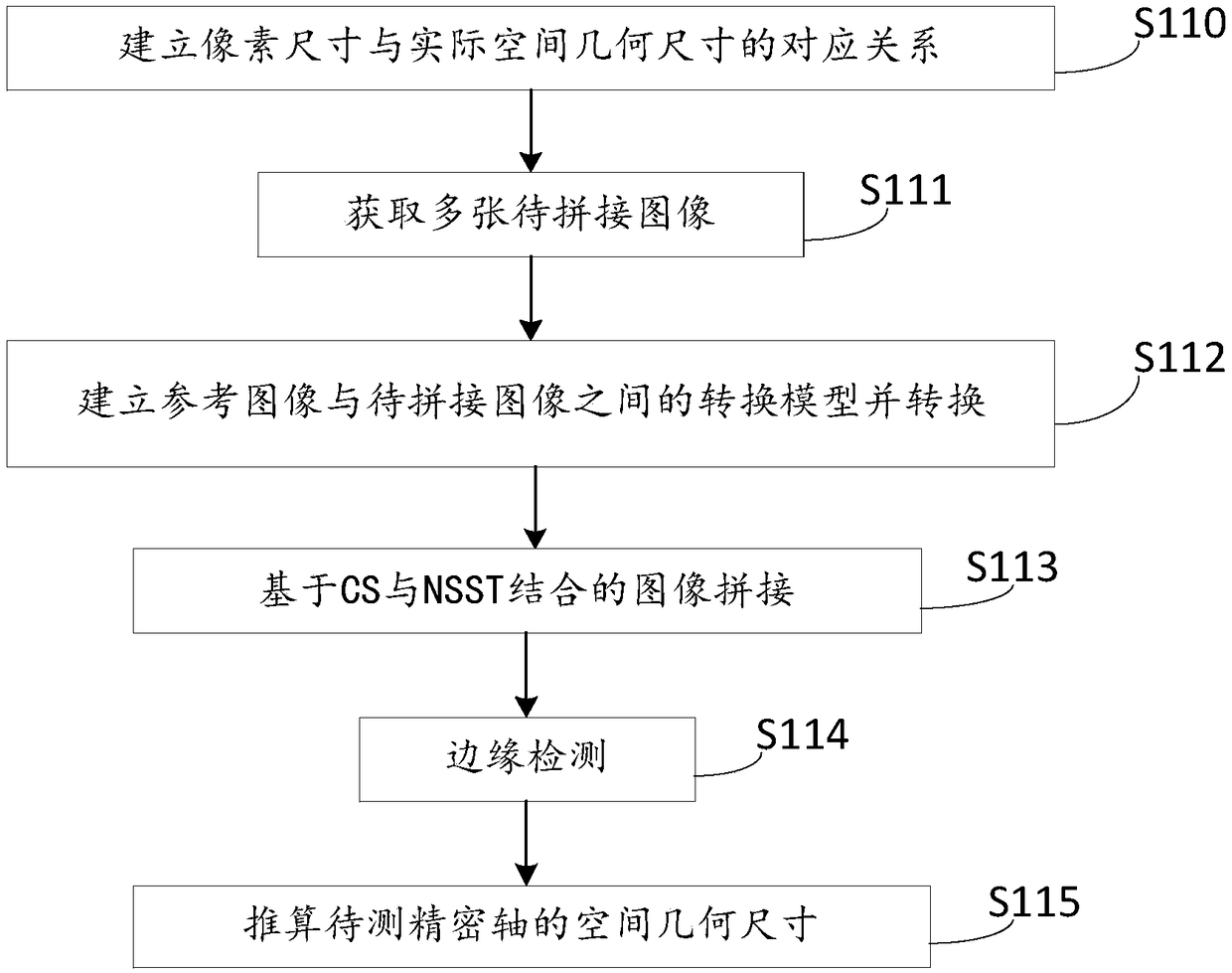
[0053] Aiming at the current status of traditional contact measurement with low efficiency, high false detection rate, and difficulty in realizing automatic control of machining process, the present invention proposes a slender precision axis high-prec...


PUM


Abstract

The invention particularly discloses a visual identification-based precise shaft size measurement method, apparatus and system. The method comprises the steps of establishing a mapping relationship between a pixel size and an actual spatial geometric size of a to-be-measured precise shaft; obtaining multiple to-be-spliced precise shaft images; building a conversion model between a reference imageand the to-be-spliced images to perform conversion; based on CS and NSST algorithm combination, performing splicing on the converted to-be-spliced images, and performing fusion to form a whole image of the to-be-measured precise shaft; and for the fused whole image, performing pixel level edge tracking and preliminary locating by using a multilevel filtered interested edge detection method firstly, then based on Sobel operator and least square curve fitting combination, obtaining sub-pixel-precision edges, and according to the detected edges and the mapping relationship, calculating the spatial geometric size of the to-be-measured precise shaft. According to the method, the apparatus and the system, the image splicing data processing amount is effectively reduced; the detection efficiencyis improved; and real-time online detection can be performed.

Description

technical field [0001] The invention relates to the technical field of parts detection based on machine vision, in particular to a precision shaft dimension measurement method, device and system based on vision recognition. Background technique [0002] The research on parts detection based on machine vision began to rise in the 1990s, and now it has gradually entered various industrial fields, and the measurement methods and methods have also been developed rapidly. Machine vision is to use machines instead of human eyes to make measurements and judgments. Through the image capture device CMOS or CCD, the captured target is converted into an image signal, which is sent to a dedicated image processing system. According to pixel distribution, brightness, color and other information, it is transformed into Digitized signals; the image system performs various operations on these signals to extract the characteristics of the target, and then controls the on-site equipment action...

Claims


Application Information

Patent Timeline
Patent Type & Authority Applications(China)
IPC IPC(8): G06T7/62G06T7/64G06T7/60G06T3/40G06T7/13G01B11/00
CPCG01B11/00G06T3/4038G06T7/60G06T2207/30164G06T7/13G06T7/62G06T7/64
Inventor 谢昕谢铭烨胡锋平王伟如江勋绎
Owner EAST CHINA JIAOTONG UNIVERSITY
Why Eureka
Try Eureka