Annular laser resonant cavity diaphragm adjustment system and adjustment method thereof

A technology of laser resonator and ring resonator, which is applied to lasers, laser components, phonon exciters, etc., can solve problems such as difficult assembly results, reduce the influence of human subjective factors, and achieve accurate detection results

Active Publication Date: 2018-07-17
XIAN UNIV OF TECH
View PDF8 Cites 10 Cited by
  • Summary
  • Abstract
  • Description
  • Claims
  • Application Information

AI Technical Summary

Problems solved by technology

Due to the measurement of microscopic dimensions, it is very difficult to ensure stable, reliable and consistent assembly results due to the influence of observation angle, operation proficiency, laser mode status and subjective factors of workers.

Method used


Image

  • Annular laser resonant cavity diaphragm adjustment system and adjustment method thereof

Examples


Embodiment Construction

[0021] The present invention will be described in detail below with reference to the drawings and specific embodiments.

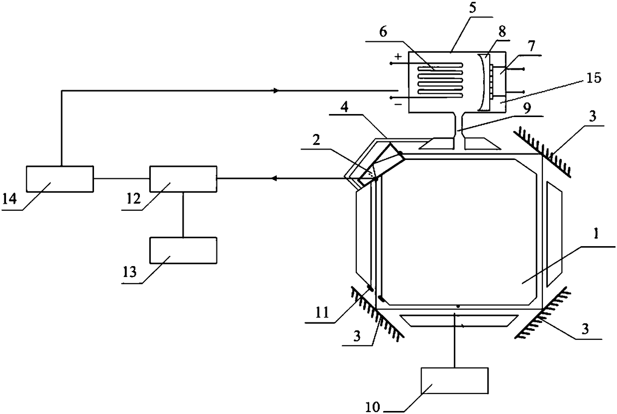
[0022] The present invention is a ring laser resonator diaphragm installation and adjustment system, such as figure 1 As shown, it includes a ring resonator cavity 1 to be assembled fixed on a base. A laser pump source 10 is arranged outside the side of the ring resonator cavity 1 filled with He-Ne gain gas. A prism 2 is arranged on one corner of the cavity 1, and a mirror 3 is arranged on the other three corners of the ring resonator cavity 1, and a patch outer diaphragm 11 is installed on the inner side of any mirror 3, along the prism 2 A photodetector 12 is provided in the horizontal direction of the emitted laser beam. The photodetector 12 is supported by a three-dimensional adjusting bracket 13. The photodetector 12 is connected with a laser frequency control box 14 through a wire, and the laser frequency control box 14 is connected with a frequency serv...


PUM


Abstract

The invention discloses an annular laser resonant cavity diaphragm adjustment system. The annular laser resonant cavity diaphragm adjustment system comprises a to-be-assembled annular resonant cavitybody fixed on a substrate; a laser pumped source is arranged outside one side of the annular resonant cavity body; a prism is arranged on one corner of the annular resonant cavity body while reflecting mirrors are arranged on the other three corners respectively; a photoelectric detector is arranged in the horizontal direction of a laser beam emitted by the prism; and the photoelectric detector isconnected with a laser frequency control box and a frequency server through a wire in sequence. An adjustment method comprises the steps of enabling the laser beam emitted by the annular laser resonant cavity to pass through the prism to output light at a brewster angle, and enabling the output light to come to the photosensitive surface of the photoelectric detector in an aligned manner firstly,next, opening the laser frequency control box, performing modal state scanning and frequency stabilizing, and detecting the assembling position of the diaphragm according to the voltage change amountof the laser pumped source before and after diaphragm assembling. The system is simple in detection process, quick in processing, and accurate in assembling result.

Description

Technical field [0001] The invention relates to the technical field of precision assembly, in particular to a ring laser resonant cavity diaphragm assembly and adjustment system, and also to an assembly method of the system. Background technique [0002] Ring lasers are the core devices in applications such as laser gyroscopes, laser gravimeters, and spectrum detection. For the coherent detection laser source with high performance and high stability requirements-ring lasers, the diaphragm restricts the high-order transverse mode of the resonator to vibrate and controls the lowest loss state that meets the requirements of the mode. It is directly related to the working time of this type of laser The accuracy and stability. This kind of ring laser has very high requirements for the assembly position accuracy of the diaphragm. Generally, the position error of the micron level is enough to affect the interference detection accuracy and working stability. At present, the traditional...

Claims


Application Information

Patent Timeline
Patent Type & Authority Applications(China)
IPC IPC(8): H01S3/081H01S3/083H01S3/10
CPCH01S3/0815H01S3/083H01S3/10061
Inventor 刘健宁连天虹寇科
Owner XIAN UNIV OF TECH
Why Eureka
Try Eureka