Supercharge Your Innovation With Domain-Expert AI Agents!

Multifunctional plate bending machine for construction

A plate rolling machine and multifunctional technology, which is applied in the field of multifunctional plate rolling machines for construction, can solve the problems of waste, a lot of manpower and material resources, and short use cycle of construction sites.

Inactive Publication Date: 2018-07-20
龙岩中天水泥制品有限公司
View PDF0 Cites 0 Cited by
  • Summary
  • Abstract
  • Description
  • Claims
  • Application Information

AI Technical Summary

Problems solved by technology

[0003] Since the plate rolling machine for construction often needs to change the application site, there is no need for an overly high-end plate rolling machine. Due to the large demand for various types of construction sites, especially for the curling and bending of steel bars and steel plates, the demand is relatively large, but the actual demand The precision is not as high as that of the mechanical industry, and the use is also required to be simple, fast and convenient.
For these different simple needs, different construction machinery is needed, but the construction site has a short service life. If it is configured according to the needs, it will require a variety of different construction machinery and equipment, which will cause a lot of waste. Therefore, according to the needs of the construction site, there is a lack of one A plate rolling machine for construction with various functions, simple structure and convenient relocation
[0004] The diameter of the existing plate rolling machine is relatively fixed. When adjustment is required, the process is complicated and the adjustment content required to skip is complicated, requiring a lot of manpower and material resources, and the efficiency is low.

Method used


Image

  • Multifunctional plate bending machine for construction
  • Multifunctional plate bending machine for construction
  • Multifunctional plate bending machine for construction

Examples


Embodiment Construction

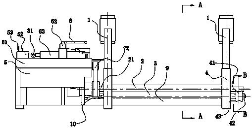
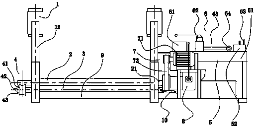
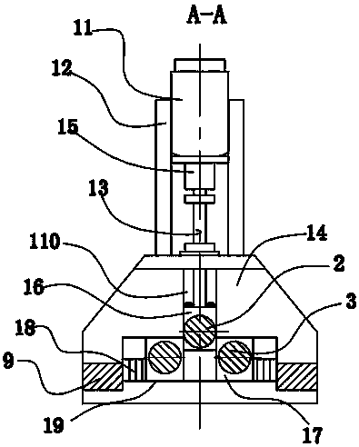
[0021] see Figure 1-Figure 5 As shown, the technical solution adopted in this specific embodiment is: it consists of two plate bending machine columns 1, an upper roller 2, two lower rollers 3, a side circular die set 4, a bending workbench 5, and a hydraulic workbench 6. The main driving device 7, the clutch 8, and the main beam 9 are composed. The two columns 1 of the plate bending machine are fixedly connected by the two main beams 9. The upper roller 2 and the two lower rollers 3 are arranged between the two columns 1 of the plate bending machine. , the two lower rollers 3 are arranged side by side, the upper roller 2 is arranged above the middle position of the two lower rollers 3; the side circular die module 4 is arranged on the right side of the right column of the plate rolling machine column 1 and is coaxial with the two lower rollers 3 The main driving device 7 is provided with the left side of the left column of the coiling machine column 1, the main driving devic...


PUM


Abstract

The invention relates to auxiliary equipment for a construction site, in particular to a multifunctional plate bending machine for construction. Two columns of the plate bending machine are fixedly connected through two main cross beams, and an upper roller and two lower rollers are arranged between the two columns of the plate bending machine; the two lower rollers are arranged side by side, andthe upper roller is arranged above the position between the two lower rollers; a side circular die set is arranged on the right side of the right column of the plate bending machine, and is coaxial with the two lower rollers; a main driving device is arranged on the left side of the left column of the plate bending machine, and connected to a main shaft of the upper roller through belt transmission and a clutch; and the right side of the clutch is provided with a bending workbench which is provided with a hydraulic workbench. The multifunctional plate bending machine is applicable for different working environments, such as the construction site, and working environments frequently moved or changed; and even for the working environments frequently moved or shifted, the working efficiency can also be ensured, and the equipment can be damaged.

Description

technical field [0001] The invention relates to an auxiliary equipment for a construction site, in particular to a multifunctional plate rolling machine for a construction. Background technique [0002] The upper roll of the symmetrical plate rolling machine is at the symmetrical position in the center of the two lower rolls. The hydraulic oil in the hydraulic cylinder acts on the piston to perform vertical lifting movement. The final gear of the main reducer drives the gears of the two lower rolls to mesh and rotate together to roll the plate. Provide torque. The flat plastic metal plate of the plate rolling machine passes between the three working rolls (two lower rolls and one upper roll) of the plate rolling machine. With the help of the pressing down of the upper roll and the rotation of the lower roll, the metal plate passes through multiple passes. Continuous bending (the inner layer is compressed and deformed, the middle layer is unchanged, and the outer layer is st...

Claims


Application Information

Patent Timeline
IPC IPC(8): B21F1/00B21D5/14
CPCB21F1/00B21D5/14
Inventor 吴祖祥
Owner 龙岩中天水泥制品有限公司
Features
  • R&D
  • Intellectual Property
  • Life Sciences
  • Materials
  • Tech Scout
  • Unparalleled Data Quality
  • Higher Quality Content
  • 60% Fewer Hallucinations
Learn More