Double-fixture drilling machine with drill bit conveying mechanism

A technology of conveying mechanism and drilling machine, applied in boring/drilling, drilling/drilling equipment, clamping and other directions, can solve the problems of low processing efficiency, high processing cost, high labor intensity, etc.

Pending Publication Date: 2018-07-20
重庆安永德锐科技有限公司
View PDF0 Cites 4 Cited by
  • Summary
  • Abstract
  • Description
  • Claims
  • Application Information

AI Technical Summary

Problems solved by technology

[0003] Most of the existing drilling devices have a relatively simple structural design, and can only hold one workpiece at a time for drilling operations, and after the fixture is damaged, it can only be replaced in situ, and there is no spare fixture that can be called in time, resulting in low processing efficiency and labor intensity. Large, high processing cost, in addition, the horizontal position of the drill bit is fixed, resulting in the inability to adjust the horizontal position of the drill bit at will, which brings certain limitations to the drilling operation

Method used


Image

  • Double-fixture drilling machine with drill bit conveying mechanism
  • Double-fixture drilling machine with drill bit conveying mechanism
  • Double-fixture drilling machine with drill bit conveying mechanism

Examples


Embodiment Construction

[0046] In order to enable those skilled in the art to better understand the present invention, the technical solution of the present invention will be further described below in conjunction with the accompanying drawings and embodiments.

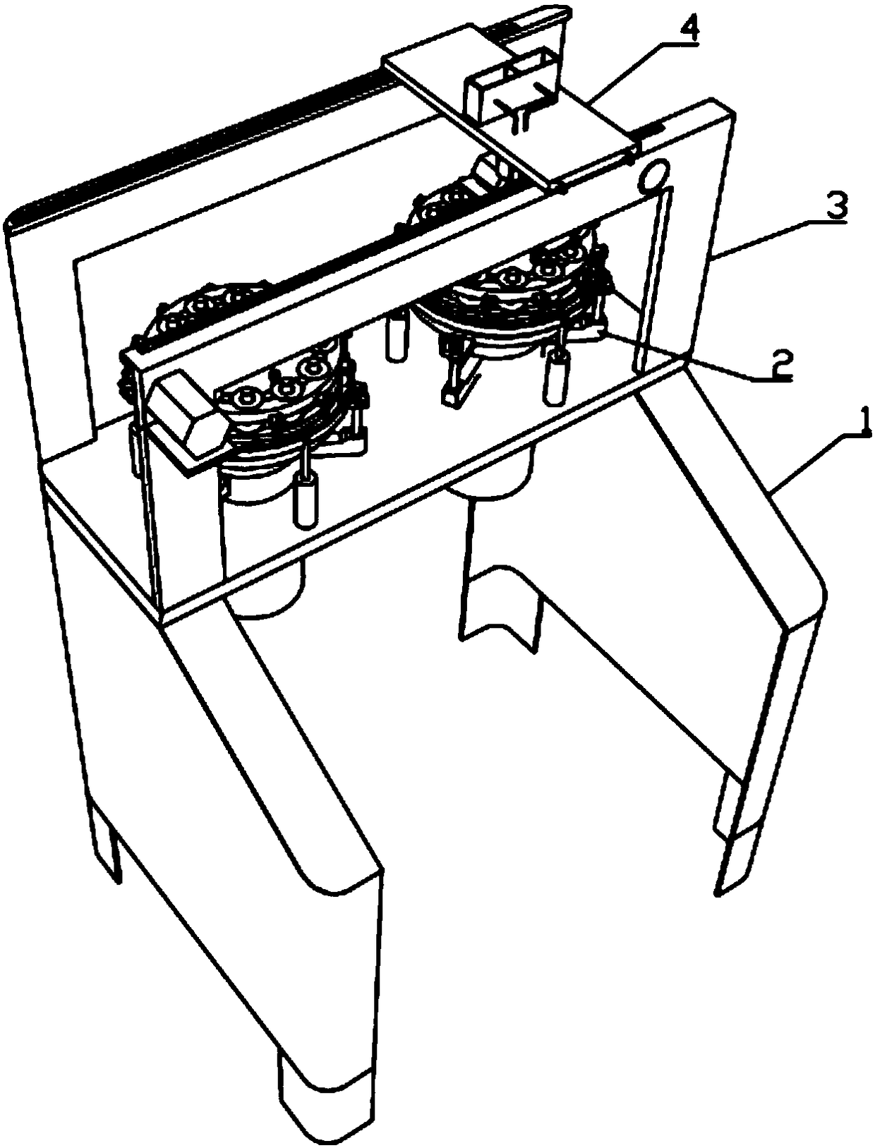
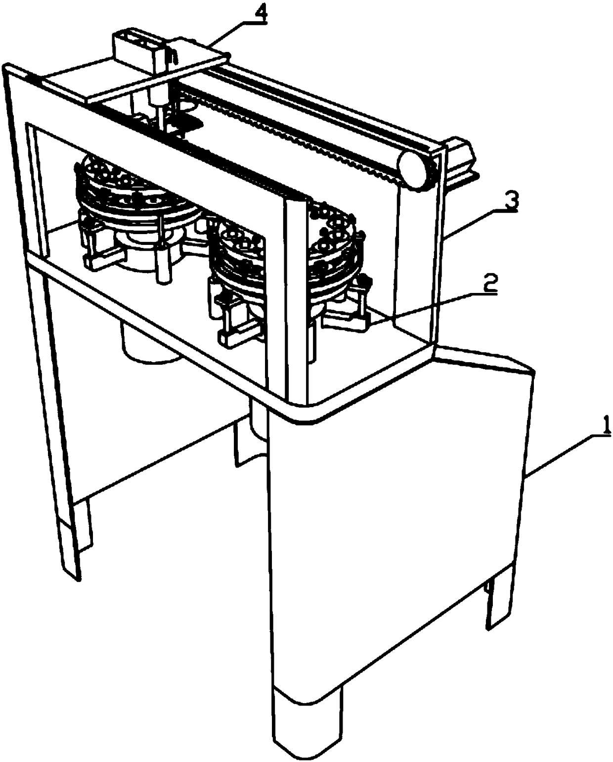
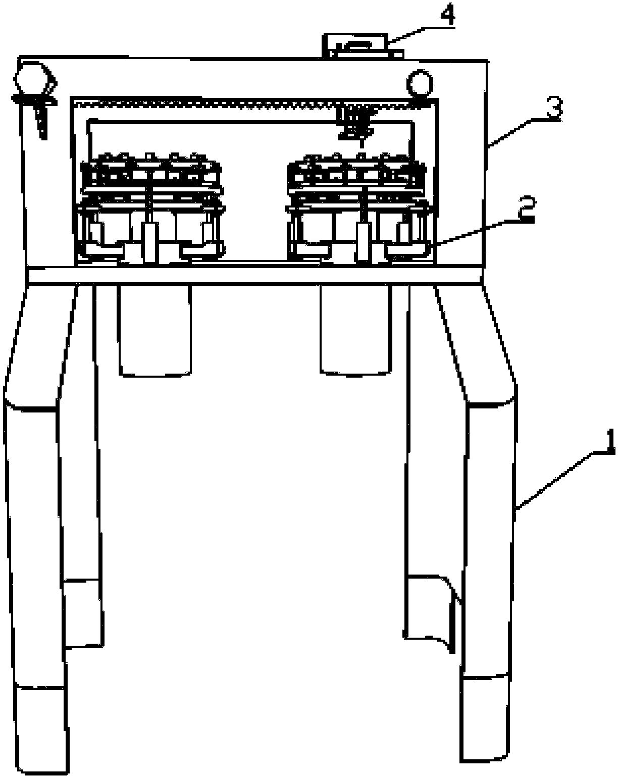
[0047] like Figure 1 to Figure 27 As shown, the double-clamp drilling machine with the drill transmission mechanism of the present invention includes an operation table 1, clamps 2, drill transmission mechanism 3 and drilling trolley 4;

[0048] The console 1 includes a left support assembly and a right support assembly, the left and right support assemblies are symmetrical in structure, the right support assembly includes a right baffle plate 10, the cross section of the right baffle plate 10 is U-shaped and the opening is left, and the right baffle plate 10 is The bottom surface of the board 10 is horizontal, and two legs 11 are fixedly installed at the front and rear two bends. The middle and rear parts of the top surface of the right ba...


PUM

PropertyMeasurementUnit
heightaaaaaaaaaa

Abstract

The invention belongs to the technical field of workpiece drilling, and particularly relates to a double-fixture drilling machine with a drill bit conveying mechanism. The double-fixture drilling machine with the drill bit conveying mechanism comprises an operating table, fixtures, the drill bit conveying mechanism and a drilling trolley, wherein the operating table comprises a left supporting assembly and a right supporting assembly; the structures of the left supporting assembly and the right supporting assembly are left-and right symmetrical; the right supporting assembly comprises a rightbaffle plate; a cross section of the right baffle plate is in a U shape; an opening of the right baffle plate is leftward; the bottom surface of the right baffle plate is horizontal; two support legsare fixedly arranged on two front and back bending parts of the right baffle plate; the middle back part of the top surface of the right baffle plate is in a horizontal shape; the middle front part ofthe top surface of the right baffle plate is provided with a slope surface high in back and lower in front from back to front; an included angle between the slope surface and the horizontal bottom surface is 30 degrees to 45 degrees; a sealing plate capable of sealing the top opening of the right baffle plate is detachably arranged on the top surface of the right baffle plate; a table top plate is fixedly arranged on the middle back parts of the top surfaces of the left supporting assembly and the right supporting assembly; and two assembling holes are formed in the table top plate.

Description

technical field [0001] The invention belongs to the technical field of workpiece drilling, and in particular relates to a double-clamp drilling machine with a drill transmission mechanism. Background technique [0002] The operation of using a drill to process holes in solid materials is called drilling. The hole processing of various parts is completed by machine tools such as turning, boring, and milling, and a large part is done by fitters using drilling machines and drilling tools (drills, reaming drill, reamer, etc.) completed. When drilling a hole on a drilling machine, under normal circumstances, the drill bit should complete two movements at the same time: the main movement, that is, the rotational movement of the drill bit around the axis (cutting movement); the auxiliary movement, that is, the linear movement of the drill bit toward the workpiece along the axis direction ( feed movement). [0003] Most of the existing drilling devices have a relatively simple str...

Claims


Application Information

Patent Timeline
Patent Type & Authority Applications(China)
IPC IPC(8): B23Q3/06B23Q11/00B23Q11/10B23B39/14
CPCB23Q3/06B23B39/14B23Q11/0078B23Q11/10
Inventor 陈康俊
Owner 重庆安永德锐科技有限公司
Why Eureka
Try Eureka