Automatic perforating equipment for bills

A kind of punching equipment and ticket technology, which is applied to the device for coating liquid on the surface, metal processing, coating, etc., can solve the problems of inaccurate punching, non-punching, low punching efficiency, etc.

Inactive Publication Date: 2018-07-20
重庆华康印务有限公司
View PDF6 Cites 1 Cited by
  • Summary
  • Abstract
  • Description
  • Claims
  • Application Information

AI Technical Summary

Problems solved by technology

At present, the existing bill punching device often has the problem of not being able to punch through, and the punching efficiency is low, wasting time, and the punching is not accurate

Method used


Image

  • Automatic perforating equipment for bills
  • Automatic perforating equipment for bills
  • Automatic perforating equipment for bills

Examples


Embodiment Construction

[0018] The following is further described in detail through specific implementation methods:

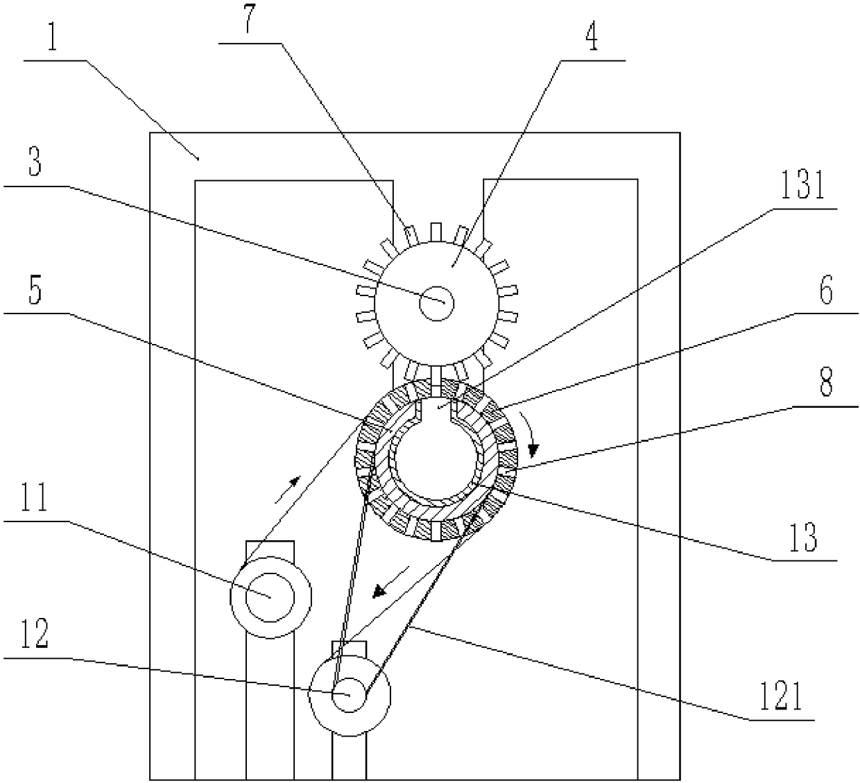
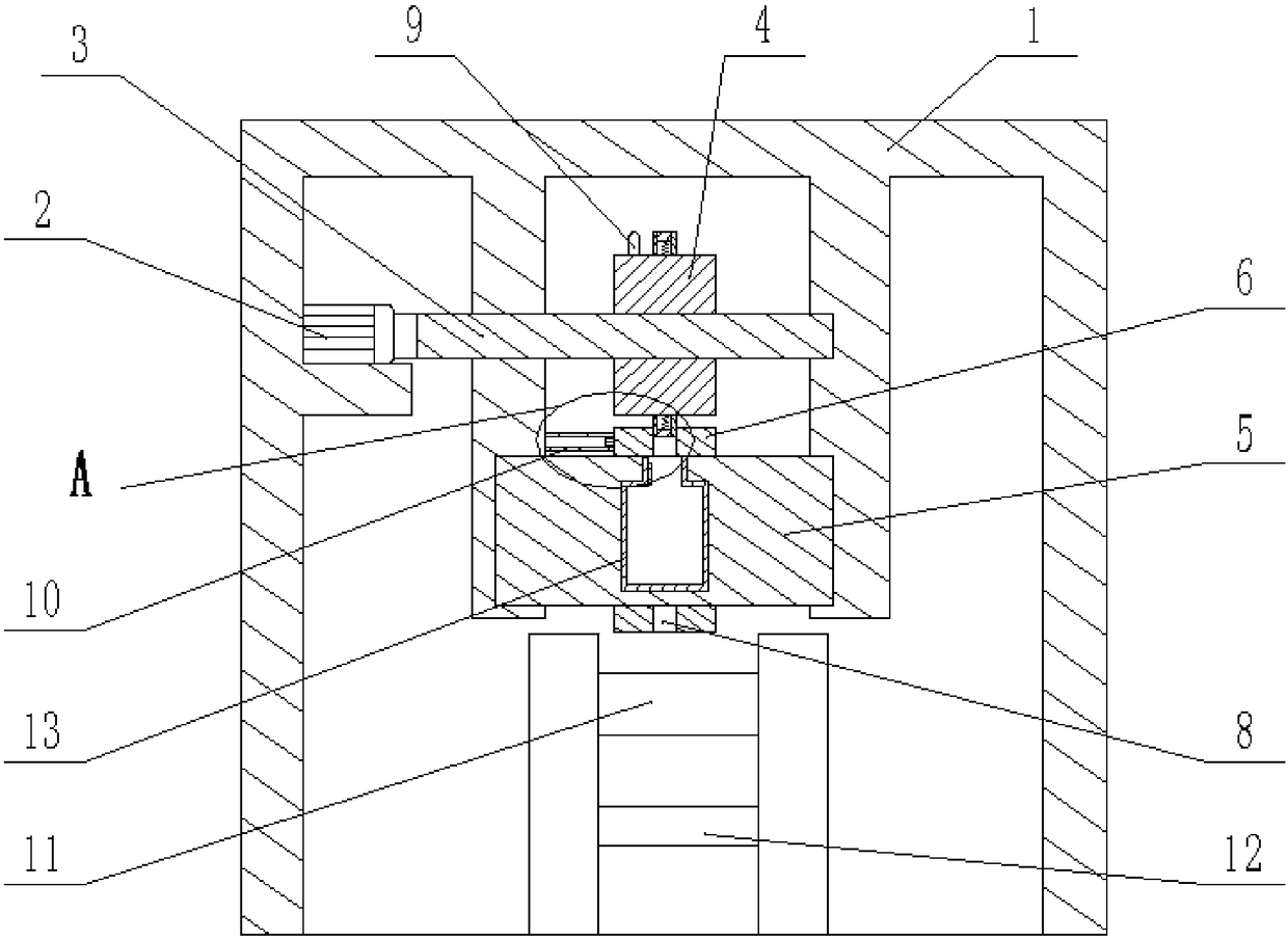
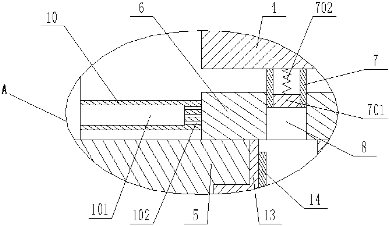
[0019] The reference signs in the drawings of the description include: frame 1, motor 2, first rotating shaft 3, punching disk 4, second rotating shaft 5, punching ring 6, punching head 7, push block 701, extension spring 702, Drilling channel 8, marking pen 9, gluing shaft 10, cavity 101, glue outlet 102, paper feed roller 11, paper delivery roller 12, belt 121, collection box 13, collection port 131, electromagnet 14.

[0020] The embodiment is basically as attached figure 1 , attached figure 2 And attached image 3 shown, among them, attached figure 1 Middle second rotating shaft 5 and perforated ring 6 take vertical plane as cutting plane, attach figure 2 The Nakamoto device takes the vertical plane where the 3 axes of the first rotating shaft are located as the cutting plane:

[0021] Automatic punching equipment for bills, including a frame 1, a punching unit, a gluing u...


PUM


Abstract

The invention belongs to the technical field of perforating, and particularly relates to automatic perforating equipment for bills. The automatic perforating equipment comprises a conveying unit, a perforating unit and a marking unit; the conveying unit comprises a paper conveying roller and a paper receiving roller; the perforating unit comprises a motor, a perforating disc and a perforating ring; the motor is connected with the perforating disc; the side wall of the perforating disc is provided with a plurality of perforating heads; the side wall of the perforating ring is provided with a plurality of perforating channels matched with the perforating heads; the perforating disc is engaged with the perforating ring through the perforating heads and the perforating channels; the perforating ring is further provided with a collecting box for collecting waste paper, and a glue smearing rod for bonding edges of the bills; a cavity for containing hot melt glue is formed in the glue smearing rod, and a resistance wire for melting the hot melt glue is arranged on the glue smearing rod; and the marking unit comprises a plurality of marking pens arranged on the side wall of the perforatingdisc, and the number of drill bits between the adjacent marking pens is equal to that of holes needing to be perforated. Through the scheme, the bill perforating efficiency is effectively improved, and the phenomenon that the bills are not completely perforated is avoided.

Description

technical field [0001] The technical field of punching of the present invention, in particular relates to automatic punching equipment for bills. Background technique [0002] Bills are often seen in daily life. Usually, there are a row of holes on both sides of the bill. These two rows of holes are designed for printer positioning and paper feeding during the printing process of bills. At the same time, it is convenient for the computer to print out bills with continuous ticket numbers. At present, the existing bill punching device often has the problem of not being able to punch through, and the punching efficiency is low, wasting time, and the punching is not accurate. Contents of the invention [0003] The object of the present invention is to provide an automatic punching device for bills, so as to improve the punching effect of bills. [0004] In order to achieve the above object, the basic solution of the present invention is: an automatic punching device for bills...

Claims


Application Information

Patent Timeline
IPC IPC(8): B26F1/00B26D7/06B26D7/18B26D7/26B26D7/27B26D7/32B26D7/34B05C1/08B05C1/00
CPCB05C1/003B05C1/08B26D7/06B26D7/1818B26D7/2614B26D7/27B26D7/32B26D7/34B26F1/00
Inventor 吴仁本
Owner 重庆华康印务有限公司
Why Eureka
Try Eureka