Long-life driving device for high-speed railway locomotive

A technology for high-speed railways and driving devices, which is applied to transmission devices driven by electric motors, railway vehicles, locomotives, etc., which can solve problems such as unfavorable driving device long-life operation, increased friction, and damage to pantographs, so as to prevent friction Increase, achieve long-life use, and prevent damage

Inactive Publication Date: 2018-07-20
ZHENGZHOU RAILWAY VOCATIONAL & TECH COLLEGE
View PDF4 Cites 0 Cited by
  • Summary
  • Abstract
  • Description
  • Claims
  • Application Information

AI Technical Summary

Problems solved by technology

[0004] During the operation of high-speed railway locomotives, because they often need to go uphill and downhill, and enter and exit tunnels, etc., this will easily lead to an increase in the friction between the pantograph and the power grid, which will lead to damage to the pantograph; on the other hand, in the speed In the process of sudden increase, the speed of the motor cannot effectively adapt to the sudden change of speed, which can easily lead to damage to the motor. It is necessary to frequently repair and replace the pantograph and traction motor of the high-speed railway locomotive, which is not conducive to the long-life operation of the drive device.

Method used


Image

  • Long-life driving device for high-speed railway locomotive
  • Long-life driving device for high-speed railway locomotive
  • Long-life driving device for high-speed railway locomotive

Examples


Embodiment 1

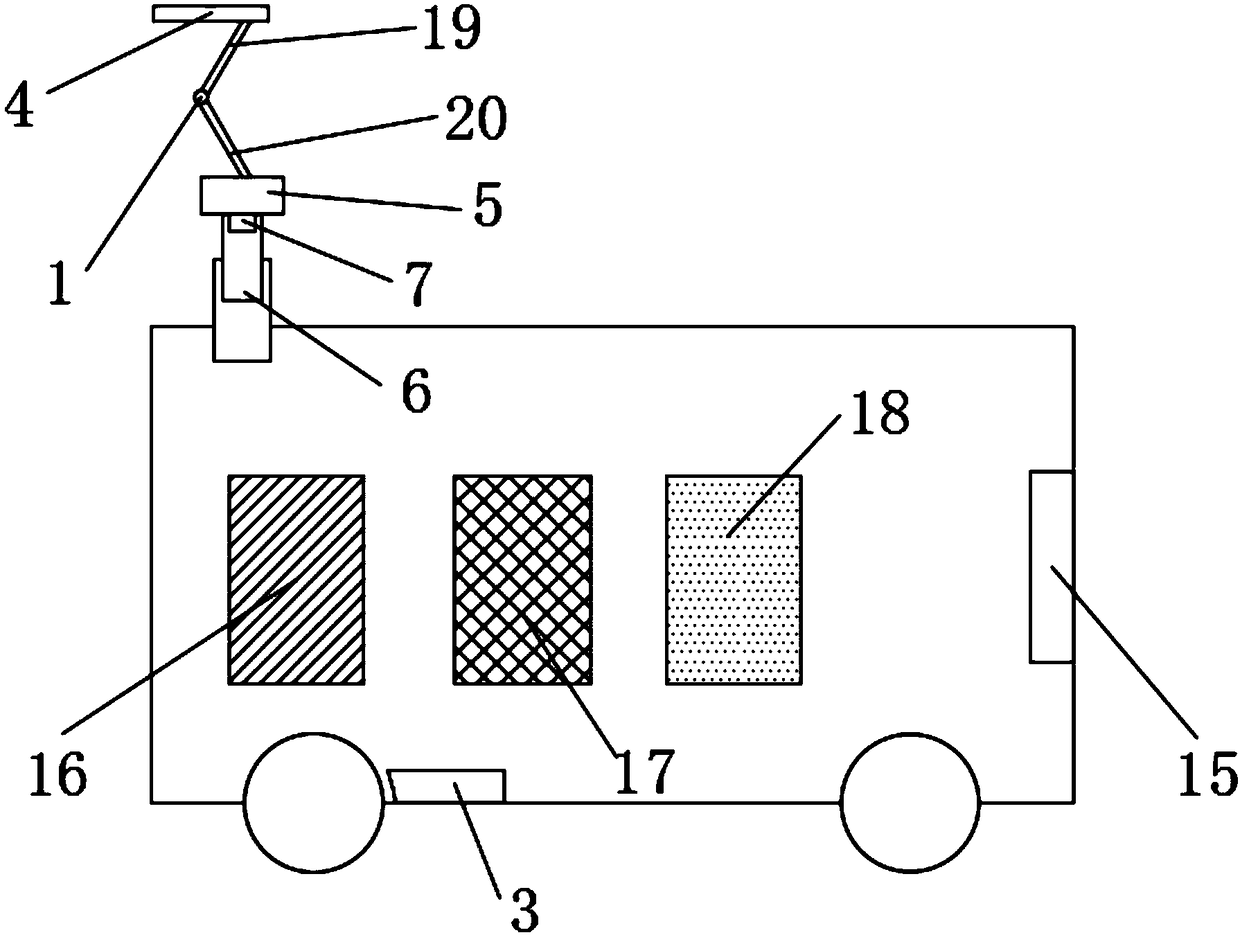
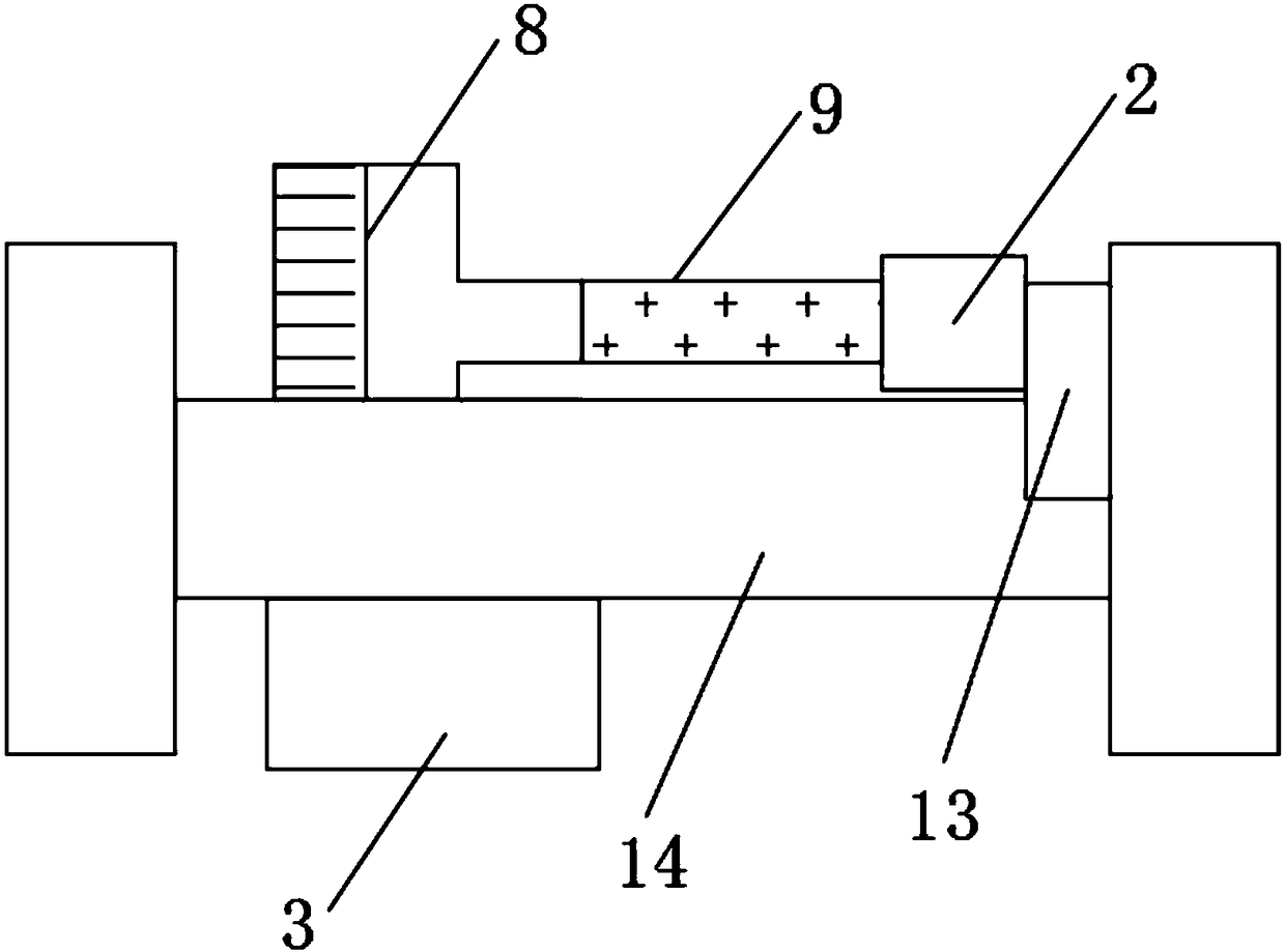
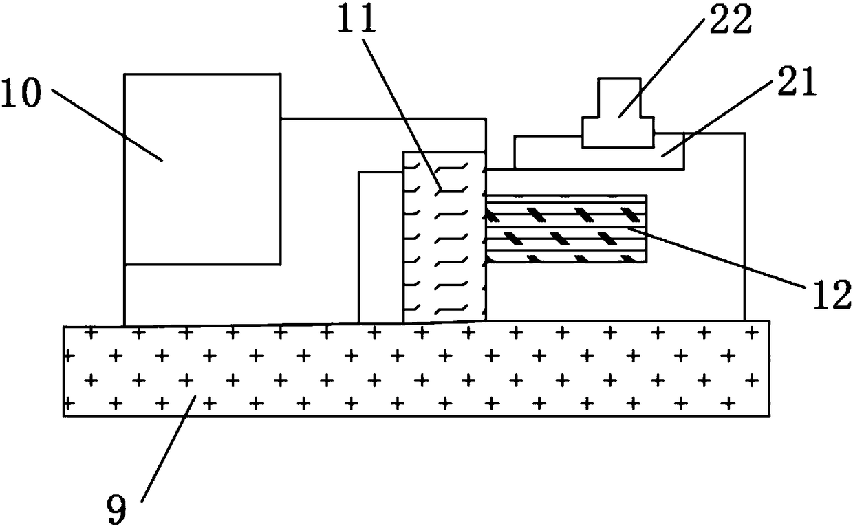
[0036] The present invention provides such Figure 1-3 The shown long-life drive device for a high-speed railway locomotive includes a pantograph 1, an electromagnetic clutch 2 and a speedometer 3, the upper part of the pantograph 1 is provided with a slide plate 4, and the lower part of the slide plate 4 is connected with A base 5, an electric telescopic rod 6 is installed on the bottom of the base 5, a pressure sensor 7 is installed inside the electric telescopic rod 6, and the pantograph 1 is electrically connected with a traction motor 8, and the traction motor 8 The driving end is connected with a driving gear 9, and the end side of the driving gear 9 is connected with an electromagnetic clutch 2 through a driven gear 10. The inside of the electromagnetic clutch 2 is provided with a friction plate 11, and the friction plate 11 is made of ferrous metal. The end side of the friction plate 11 is provided with a coil 12 for energizing to generate magnetic force. The driven ge...

Embodiment 2

[0048] A long-life driving device for a high-speed railway locomotive, comprising a pantograph 1, an electromagnetic clutch 2 and a speedometer 3, the upper part of the pantograph 1 is provided with a slide plate 4, and the lower part of the slide plate 4 is connected with a base 5, An electric telescopic rod 6 is installed on the lower part of the base 5, and a pressure sensor 7 is installed inside the electric telescopic rod 6. The pantograph 1 is electrically connected to a traction motor 8, and the driving end of the traction motor 8 is connected to There is a driving gear 9, the end side of the driving gear 9 is connected with an electromagnetic clutch 2 through a driven gear 10, the inside of the electromagnetic clutch 2 is provided with a friction plate 11, the friction plate 11 is made of ferrous metal, and the friction plate 11 is made of ferrous metal. A coil 12 is provided on the end side of the sheet 11 for generating magnetic force when energized. The driven gear 1...

Embodiment 3

[0061] A long-life driving device for a high-speed railway locomotive, comprising a pantograph 1, an electromagnetic clutch 2 and a speedometer 3, the upper part of the pantograph 1 is provided with a slide plate 4, and the lower part of the slide plate 4 is connected with a base 5, An electric telescopic rod 6 is installed on the lower part of the base 5, and a pressure sensor 7 is installed inside the electric telescopic rod 6. The pantograph 1 is electrically connected to a traction motor 8, and the driving end of the traction motor 8 is connected to There is a driving gear 9, the end side of the driving gear 9 is connected with an electromagnetic clutch 2 through a driven gear 10, the inside of the electromagnetic clutch 2 is provided with a friction plate 11, the friction plate 11 is made of ferrous metal, and the friction plate 11 is made of ferrous metal. A coil 12 is provided on the end side of the sheet 11 for generating magnetic force when energized. The driven gear 1...


PUM


Abstract

The invention discloses a long-life driving device for a high-speed railway locomotive. The long-life driving device for the high-speed railway locomotive comprises a pantograph, an electromagnetic clutch and a speed measuring device. A sliding plate is arranged on the upper portion of the pantograph. A base is arranged on the lower portion of the sliding plate. An electric extensible rod is installed on the lower portion of the base. A pressure sensor is installed in the electric extensible rod. The pantograph is electrically connected with a traction motor. The driving end of the traction motor is connected with a driving toothed gear. The end side of the driving toothed gear is connected with the electromagnetic clutch through a driven toothed gear. A friction plate is arranged in the electromagnetic clutch. A coil is arranged on the end side of the friction plate. The driven toothed gear is connected with a gearbox in a rotating mode. The gearbox is connected with a vehicle shaft in a rotating mode. The speed measuring device is installed on one side of the vehicle shaft. According to the test of a vehicle speed and pressure condition, the long-life driving device for the high-speed railway locomotive controls the lifting of the electric extensible rod, the opening and closing of the electromagnetic clutch and the adjustment of the running of a driving device by a PCL, so that the purpose of long life can be achieved.

Description

technical field [0001] The invention belongs to the technical field of locomotive driving, and more specifically relates to a long-life driving device for high-speed railway locomotives. Background technique [0002] With the development of science and technology, my country's high-speed railway locomotives have developed rapidly, and the transformation from traditional steam locomotive traction to internal combustion engine and electric traction has gradually been realized. The traction transmission of high-speed railway locomotives is mostly electric traction transmission, and the so-called electric transmission mode is to convert externally input electric energy or self-generated energy through a complete set of electric energy conversion and transmission devices to realize the conversion of electric energy and mechanical energy. To finish driving the traction locomotive forward. [0003] The driving device of a high-speed railway locomotive is composed of pantograph, tr...

Claims


Application Information

Patent Timeline
Patent Type & Authority Applications(China)
IPC IPC(8): B60L5/20B60L5/24B61C9/38B61C17/12
CPCB61C9/38B61C17/12B60L5/20B60L5/24B60L2200/26
Inventor 张琼洁侯园园毕红雪陈然钟恩松张金瑞宋慧娟
Owner ZHENGZHOU RAILWAY VOCATIONAL & TECH COLLEGE
Why Eureka
Try Eureka