Buffering and damping device with adjustable rigidity and mounting method of buffering and damping device

A technology of shock absorbing device and rigidity, which is applied in the direction of shockproof, construction, artificial island, etc. It can solve the problems of rubber deformation hugging the guide shaft body, affecting the shock absorption effect, and non-adjustable stiffness, so as to achieve the integrity of the protection structure and the shock absorption effect Good, wide range of effects

Inactive Publication Date: 2018-07-20
QINGDAO TECHNOLOGICAL UNIVERSITY
View PDF0 Cites 3 Cited by
  • Summary
  • Abstract
  • Description
  • Claims
  • Application Information

AI Technical Summary

Problems solved by technology

[0006] The problems existing in the prior art are: the damping devices used in marine engineering are all imported from abroad at present, and the devices need to be welded to the pile legs, the installation is complicated, the volume is huge, and the cost is high, and rubber bearings are mostly used as vertical buffers The rigidity of the material cannot be adjusted, and the rubber is prone t

Method used


Image

  • Buffering and damping device with adjustable rigidity and mounting method of buffering and damping device
  • Buffering and damping device with adjustable rigidity and mounting method of buffering and damping device
  • Buffering and damping device with adjustable rigidity and mounting method of buffering and damping device

Examples


Example Embodiment

[0062] Example 1:

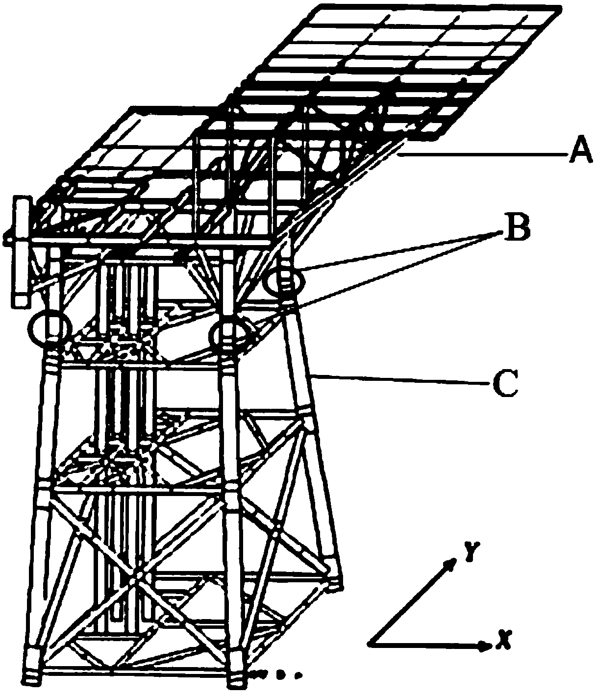
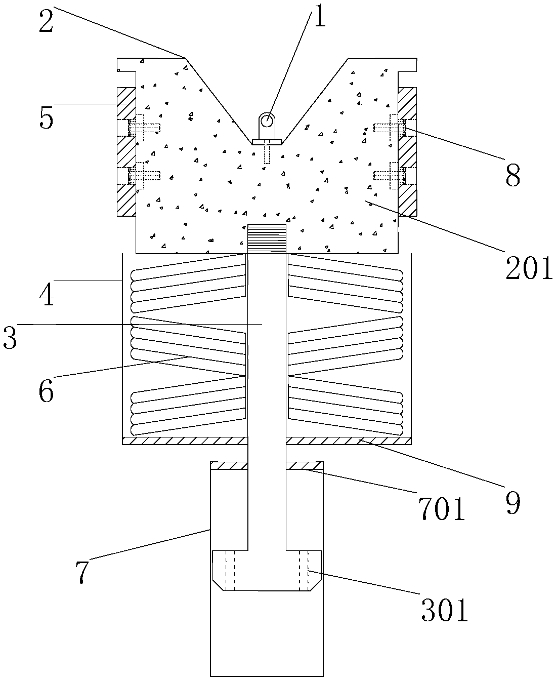
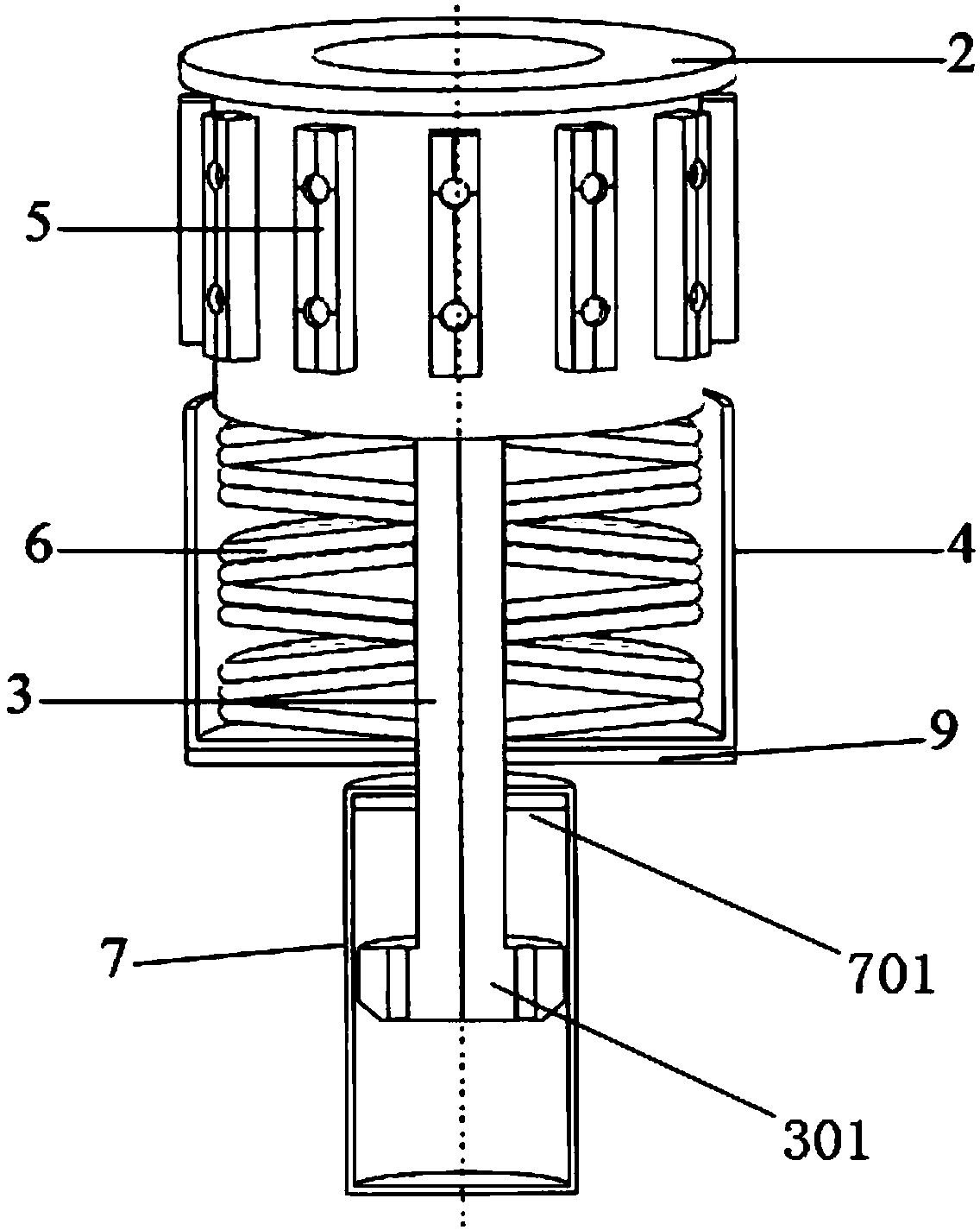
[0063] Such as figure 1 , Figure 13 , Figure 14 or Figure 15 As shown, the traditional jacket offshore platform form is selected, figure 1 A is the upper block, B is the installation position of the present invention, and C is the jacket. The shock-absorbing device of this embodiment includes a transverse shock-absorbing elastic body 5 and a conical receiver 2 arranged coaxially. Body 3 and vertical shock-absorbing module, 16 lateral shock-absorbing elastic bodies 5 are fixed on the side of the cone receiver 2 by bolts 8 at intervals. The cone receiver 2 is filled with concrete 201, and the upper part of the cone receiver 2 There is a cone opening 202, a detachable hanging plate 1 is pre-installed in the cone opening 202, the cone receiver 2 is connected to the vertical shock absorption module through the rigid shaft 3, and the vertical shock absorption module is arranged in the cone Below the receiver 2; the vertical damping module includes a coaxially arr...

Example Embodiment

[0068] Example 2:

[0069] Different from Example 1, the offshore platform in Example 2 chooses a new tube-in-tube concrete-filled steel tube offshore platform, and the installation conditions are relatively harsh, such as Figure 16 , Figure 17 , Figure 18 or Figure 19 As shown, the difference from the traditional offshore platform is that the outer diameter of the upper block duct 10 is greater than the outer diameter of the leg, and the leg form is a tube-in-pipe concrete-filled steel tube leg 18, and the device of the invention is left near the top of the leg The hollow area used. In order to solve the problem of the connection of upper and lower different cross-sections, the outer steel pipe of the leg is welded with a stiffening rib 12 and a pressure plate 13 around the circumference.

[0070] The device of the present invention is hoisted into the pipe-in-pipe concrete-filled steel tube leg 18, the shell 4 is just sitting on the sandwich concrete, and the rubber pad 9 on ...

Example Embodiment

[0075] Example 3:

[0076] In the field of prefabricated buildings, the mass of the upper block is generally smaller, and the installation environment is more stable than that of the offshore platform, so the impact generated by collision and installation is smaller. The difference between this embodiment and the first embodiment is that the viscous damper 7 is disassembled and used, which is especially suitable for the assembly of a building structure with a small superstructure. Such as Picture 20 The upper assembly unit D includes a frame beam and a steel pipe column top column 15, the lower assembly unit E includes a frame beam and a steel pipe column bottom column 16, and the assembly node B of the upper assembly unit D and the lower assembly unit E is equipped with a shock-absorbing device. Such as Figure 21 , Figure 22 with Figure 23 As shown, the limit support Ⅲ 173 of the central opening is pre-installed on the inner side of the bottom column 16 of the steel pipe col...


PUM


Abstract

The invention relates to a buffering and damping device with the adjustable rigidity and a mounting method of the buffering and damping device, and belongs to the technical field of the damping components and mounting. The buffering and damping device comprises transverse damping elastomers, a conical receiver, a rigid shaft body and a vertical damping module, wherein the conical receiver, the rigid shaft body and the vertical damping module are coaxially arranged; the transverse damping elastomers are arranged around the side face of the conical receiver at intervals, the conical receiver isconnected with the vertical damping module through the rigid shaft body, and the vertical damping module is arranged below the conical receiver; and the vertical damping module comprises a shell and abutterfly-shaped spring set, one end of the rigid shaft body is connected with the conical receiver and serve as a center guiding tube to penetrate through the butterfly-shaped spring set, and when being mounted in a large-mass and complex environment, the vertical damping module further comprises a viscous damper. The mounting process of the buffering and damping device is easy and rapid, through combined action of the transverse damping elastomers and the vertical damping module, impact energy produced by collision in the mounting process of an upper structure and a lower structure can be fully absorbed, and impact damage is maximally reduced.

Description

technical field [0001] The invention relates to a shock-absorbing device with adjustable stiffness and an installation method thereof, belonging to the technical field of shock-absorbing components and installation. Background technique [0002] The offshore platform is an important infrastructure for offshore oil and gas exploration and work and life, and is mainly composed of an upper block structure and a lower jacket structure. Usually the platform is processed and prefabricated in the onshore factory, and then transported to the designated location on the sea after completion. Combined with the hoisting operation, the jacket is first fixed by piling, and then the relative height between the upper and lower structures is properly adjusted by the floating towing method to move the upper block horizontally. Go above the lower jacket, and finally lower the upper block slowly to complete the limit installation of the upper and lower structures (the upper block and the lower ...

Claims


Application Information

Patent Timeline
IPC IPC(8): E04B1/98E02B17/00
CPCE02B17/00E02B2017/0056E04H9/0215
Inventor 张纪刚陈飞赵铁军梁海志刘菲菲王向英
Owner QINGDAO TECHNOLOGICAL UNIVERSITY
Why Eureka
Try Eureka