Secondary hanging double-pipe separate injection technology pipe column

A technology for process pipe string and outer pipe string, which is applied in the fields of production fluids, wellbore/well components, earth-moving drilling, etc. The effect of breaking through the maximum well depth limit, expanding the scope of application and improving the practical life

Pending Publication Date: 2018-07-20
CHINA PETROLEUM & CHEM CORP +1
View PDF0 Cites 0 Cited by
  • Summary
  • Abstract
  • Description
  • Claims
  • Application Information

AI Technical Summary

Problems solved by technology

However, the application of this process is restricted by the well depth, which is mainly manifested in the following: the casing specifications of onshore separate injection wells are mainly 5 1 / 2 in, limited by the size of the sleeve, the outer tube usually adopts 3 1 / 2 TBG tubing or 2 7 / 8 TBG oil pipe, the inner pipe usually adopts 1.900TBG oil pipe. When used in deep or ultra-deep wells, since the outer pipe and inner pipe are suspended at one time, the weight of the outer pipe and inner pipe respectively acts on the outer pipe hanger and inner pipe hanger at the wellhead. On the pipe hanger, the closer the oil pipe (outer pipe or inner pipe) to the wellhead, the greater the gravity load. Compared with the outer pipe, the tensile limit of the inner pipe thread is much smaller, and the limit depth that can be lowered is also lower than that of the outer pipe. It is much smaller, and there is a risk of tripping of the inner pipe near the wellhead during the running of the pipe string and the post-pipe inspection operation, resulting in the failure of the injection or the salvage operation
At the same time, because these reasons restrict the running depth of the pipe string, it is impossible or dare not to apply this technology in deep or ultra-deep wells, which limits the application range of the technology
[0003] After searching, some double-pipe split injection strings were found, but the main invention of these strings is still split injection, and none of them solves the risk of tripping of the inner pipe near the wellhead during the string running process and later inspection operations. , causing dispensing failure or salvage operation problems, in addition, no disclosed technology with the same technical solution as the present application has been found

Method used


Image

  • Secondary hanging double-pipe separate injection technology pipe column

Examples


Embodiment Construction

[0017] The detailed description and technical content of the present invention are described below with the drawings, but the drawings are only for reference and description, and are not used to limit the present invention.

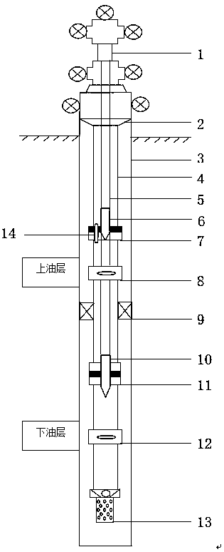
[0018] as attached figure 1 As shown, the secondary suspension double-pipe dispensing process string includes the outer pipe 4 and the inner pipe 5. The outer pipe 4 can be regarded as a whole, and other accessories are connected to it in turn, or it can be divided into multiple outer pipes, such as the first An outer tube, a second outer tube, a third outer tube, a fourth outer tube, and a fifth outer tube, and then the outer tubes are connected to other fittings between two pairs or their ends. The inner tube 5 can also be compared in this way. The inner pipe is arranged coaxially inside the outer pipe, the central cavity of the inner pipe is used as an inner water injection channel connected to the lower oil layer, and the annular space formed between...


PUM


Abstract

The invention discloses a secondary hanging double-pipe separate injection technology pipe column. The secondary hanging double-pipe separate injection technology pipe column comprises a hanging outerpipe column and a hanging inner pipe column, wherein the hanging inner pipe column is coaxially arranged inside the hanging outer pipe column. A central cavity of the hanging inner pipe column is used as an inner water injection channel communicating with a lower oil layer, and an annulus formed between the hanging inner pipe column and the hanging outer pipe column is used as an outer water injection channel communicating with an upper oil layer. The hanging outer pipe column is provided with a hanging switching overflow device for hanging the hanging inner pipe column. Two times of hangingof an inner pipe are realized, wherein the first time of hanging is carried out downhole, the second time of hanging is carried out at a wellhead, and the first time of hanging realizes that the weight of the in pipe under the hanging switching overflow device acts on an outer pipe through the hanging switching overflow device, and the second time of hanging still acts on the wellhead through a wellhead inner pipe hanger.

Description

technical field [0001] The invention relates to a water injection device for an oil field water injection well, in particular to a secondary suspension double-pipe split injection process string. Background technique [0002] For heterogeneous reservoirs, single-pipe layered water injection plays a very important role in adjusting the contradiction between layers, controlling the rise of water cut in crude oil and improving oil recovery. However, for the following four types of water injection wells with special well conditions, the single-tube separate injection process is not suitable: (1) For wells with a large water injection pressure difference between layers, the water nozzle is easy to puncture and damage, and loses the deployment function, resulting in frequent testing and adjustment ; (2) Water injection wells with serious scale fouling of downhole pipe strings often encounter obstructions in testing and deployment; (3) Distributed injection wells with well deviatio...

Claims


Application Information

Patent Timeline
Patent Type & Authority Applications(China)
IPC IPC(8): E21B43/20
CPCE21B43/20
Inventor 王宏万马珍福郭慧张卫卫孙金峰马艳洁刘晋伟刘海涛咸国旗李永康
Owner CHINA PETROLEUM & CHEM CORP
Why Eureka
Try Eureka