
Top-strengthening bottom-reinforcing two-side pressure releasing support structure and method applicable to dynamic pressure roadway

A technology for supporting structures and roadways, which is applied in tunnels, tunnel linings, earthwork drilling and mining, etc., can solve the problems of poor consideration of surrounding rock stress, short deformation period, roadway deformation, etc., so as to achieve simple and reasonable construction technology and save rework. cost effect

Active Publication Date: 2018-07-20
SHANDONG JIANZHU UNIV
View PDF4 Cites 3 Cited by
  • Summary
  • Abstract
  • Description
  • Claims
  • Application Information

AI Technical Summary

Problems solved by technology

The stress of the surrounding rock of the dynamic pressure roadway changes significantly, and the time is short, resulting in a large pressure on the surrounding rock of the roadway, serious deformation of the roadway, short deformation period, and very difficult maintenance
Existing support methods pay more attention to the increase of support strength, and do not consider the pressure relief of the surrounding rock to reduce the stress of the surrounding rock

Method used

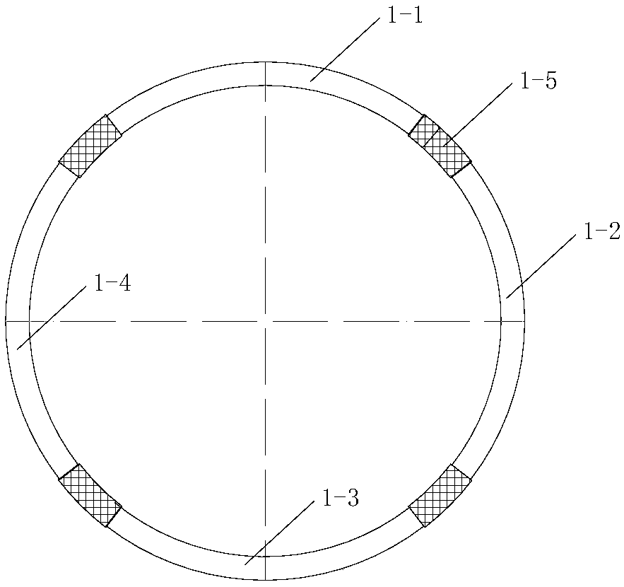
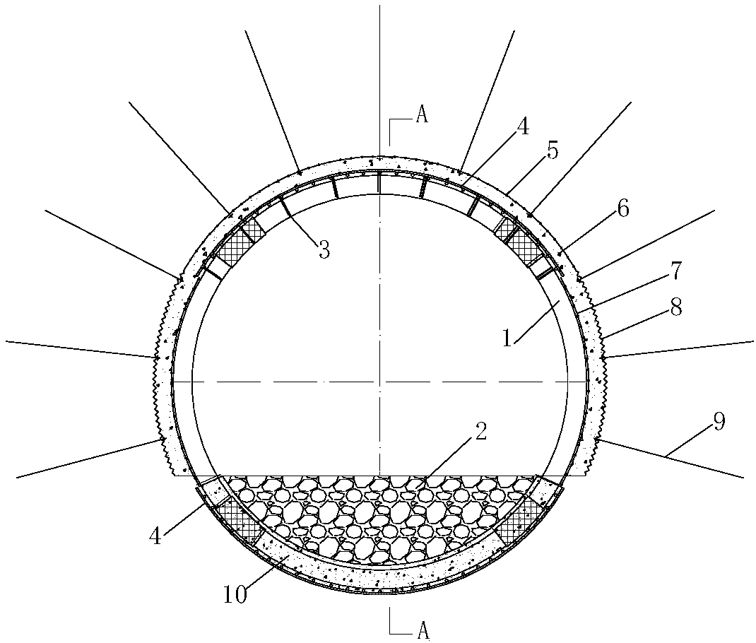
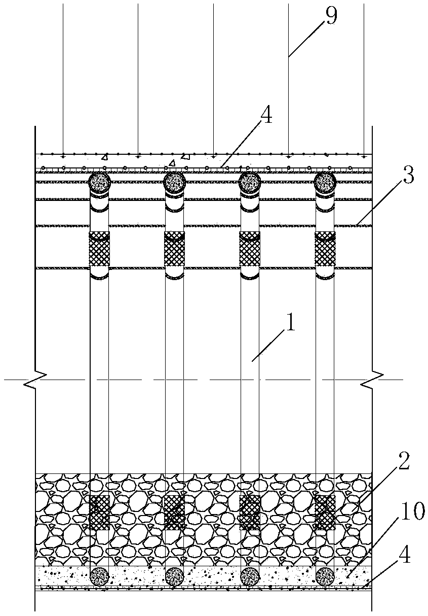

Image

  • Top-strengthening bottom-reinforcing two-side pressure releasing support structure and method applicable to dynamic pressure roadway
  • Top-strengthening bottom-reinforcing two-side pressure releasing support structure and method applicable to dynamic pressure roadway
  • Top-strengthening bottom-reinforcing two-side pressure releasing support structure and method applicable to dynamic pressure roadway

Examples


Embodiment Construction

[0053] It should be pointed out that the following detailed description is exemplary and intended to provide further explanation to the present application. Unless defined otherwise, all technical and scientific terms used herein have the same meaning as commonly understood by one of ordinary skill in the art to which this application belongs.

[0054]It should be noted that the terminology used here is only for describing specific implementations, and is not intended to limit the exemplary implementations according to the present application. As used herein, unless the context clearly dictates otherwise, the singular is intended to include the plural, and it should also be understood that when the terms "comprising" and / or "comprising" are used in this specification, they mean There are features, steps, operations, means, components and / or combinations thereof.

[0055] As introduced in the background technology, there are deficiencies in the prior art. In order to solve the...


PUM


Abstract

The invention discloses a top-strengthening bottom-reinforcing two-side pressure releasing support structure applicable to a dynamic pressure roadway. The problem that in the prior art, a dynamic pressure roadway is easily disturbed by excavation and consequently destroyed is solved. On the basis of ensuring that an original support structure is not destroyed, dynamic pressure disturbance is transferred by using the two sides to release pressure, and finally, the beneficial effect of continuous stabilizing of the roadway is achieved. According to the technical scheme, the top-strengthening bottom-reinforcing two-side pressure releasing support structure applicable to the dynamic pressure roadway takes concrete-filled steel tube brackets and anchor net spray composite support as the foundation, and support measures such as a high-strength anti-tension net and a concrete bottom arch are supplemented, so that the dynamic pressure is dealt with step by step. Top plate and bottom plate support is strengthened before the dynamic pressure appears, high-strength anti-tension steel is laid between a bracket top arc section and surrounding rock, and the tops of the brackets are connected into a whole by using a back penetrating steel wire rope; and high-strength anti-tension steel is laid between a bracket inverted bottom arch and the surrounding rock, and a concrete bottom arch is poured. The two sides are excavated to release the pressure when the dynamic pressure appears, stabilizing of the top plate and the bottom plate is ensured, and the roadway is continued to be used.

Description

technical field [0001] The invention relates to the field of underground engineering support, in particular to a pressure-relief support structure and method for a strong top and bottom two-side support structure suitable for dynamic pressure tunnels. Background technique [0002] After the mining of coal resources, the coal mining face will form a goaf, and the roof of the gob will fall, and the top of the roof will form a collapse zone, a fault zone and a bending subsidence zone, and the static pressure state of the stress field of the original rock in the mining area will be broken. The surrounding rock enters the stress redistribution and undergoes multiple redistributions. During this process, a stress concentration zone will be formed near the gob. The concentrated stress is much greater than the stress of the original rock and spreads to the nearby roadway, resulting in heavy stress in the surrounding rock of the roadway. distributed. If the support force of the road...

Claims


Application Information

Patent Timeline
Patent Type & Authority Applications(China)
IPC IPC(8): E21D11/15E21D11/10
CPCE21D11/107E21D11/152Y02E10/20
Inventor 王军郭毕钧杨立华王正泽左建平徐亮宋建新
Owner SHANDONG JIANZHU UNIV
Learn More