Eureka AIR delivers breakthrough ideas for toughest innovation challenges, trusted by R&D personnel around the world.

Method and control apparatus for operating reciprocating piston pump

一种往复活塞、控制装置的技术,应用在操控泵领域,能够解决没有公开调节策略等问题

Active Publication Date: 2018-07-20
ROBERT BOSCH GMBH
View PDF9 Cites 0 Cited by
  • Summary
  • Abstract
  • Description
  • Claims
  • Application Information

AI Technical Summary

Problems solved by technology

Although DE 10 2008 042 987 A1 describes the technical environment, no regulation strategy as proposed in this document is disclosed

Method used


Image

  • Method and control apparatus for operating reciprocating piston pump

Examples


Embodiment Construction

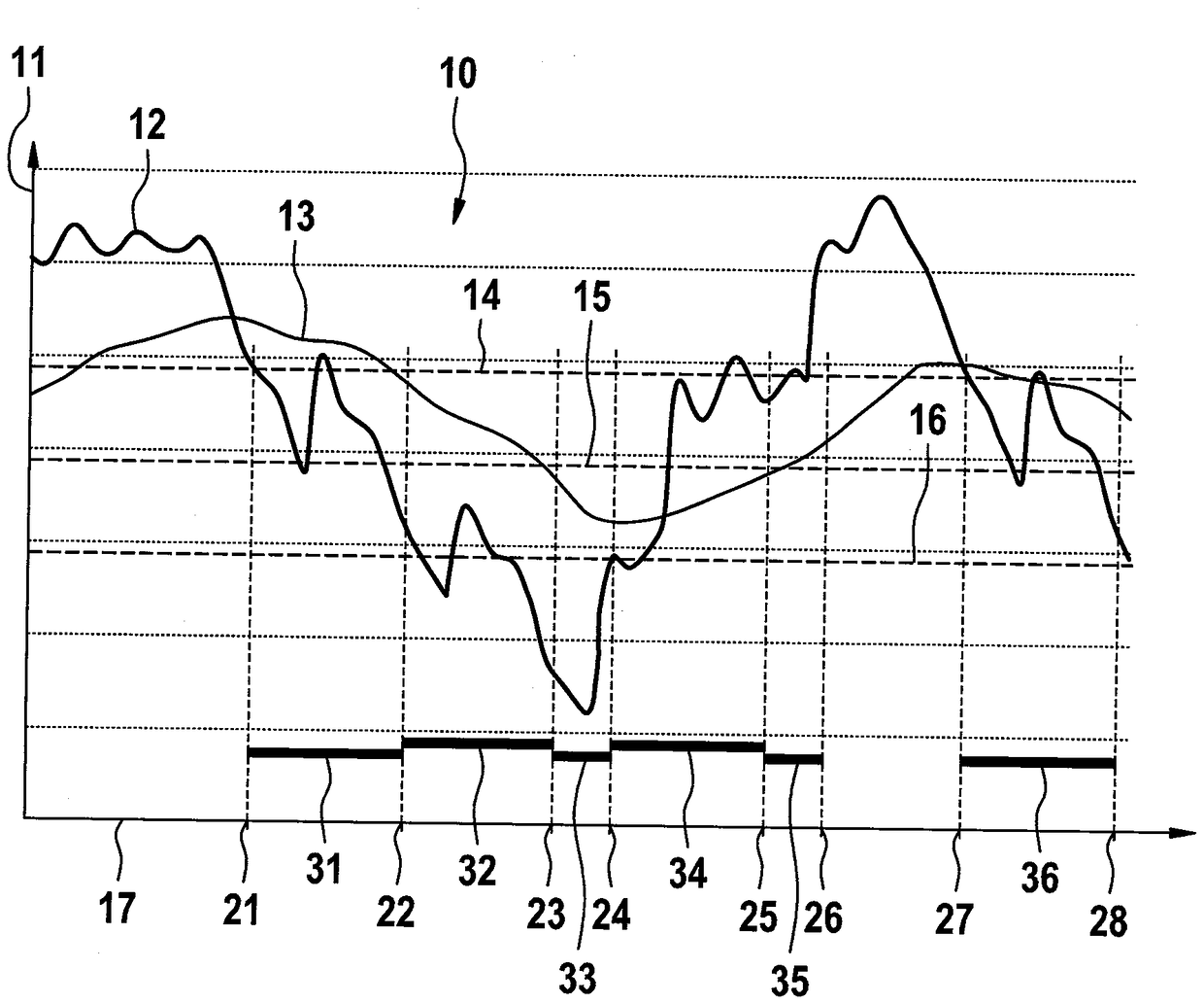
[0019] figure 1 A pressure diagram 10 with a pressure axis 11 and a time axis 17 is shown.

[0020] The pressure diagram 10 is filled with a first pressure curve 12 and a second pressure curve 13 which represent the time curve of the system pressure in a hydraulic system with a reciprocating piston pump or a diaphragm pump Alternatively, a variable derived therefrom drives a reciprocating piston pump or a membrane pump (membrane pump) with a magnetic actuator moved by the magnetic field of a solenoid coil. The reciprocating piston pump or the diaphragm pump can be installed, for example, in a dosing device for aqueous urea solution ("Ad-Blue"), in a denitration device in the exhaust gas duct of an internal combustion engine, for system pressure generation. In the exemplary embodiment, the first pressure curve 12 is generated from the system pressure by low-pass filtering. The second pressure curve 13 is obtained from the system pressure or from the first pressure curve 12 by...


PUM


Abstract

The invention relates to a method for controlling a pump. The pump is provided with a reciprocating piston or a diaphragm, and is used for generating pressure in a hydraulic system, wherein the reciprocating piston or the diaphragm is driven by an actuator driven by a magnetic field of the electromagnetic coil, and wherein the system pressure in the hydraulic system is determined. The invention further relates to a control device for executing the method. According to the invention, according to the system pressure and or at least one system pressure which is filtered in time, so as to run theelectromagnetic coil with an idle turn-off or a turn-off with fast elimination. The turn-off with idling or the turn-off with fast elimination is used in accordance with the demand, and the sound emission and the power loss of the pump can be reduced. However, a relatively high capacity can be provided when needed.

Description

technical field [0001] The invention relates to a method for operating a pump having a reciprocating piston or a diaphragm for generating pressure in a hydraulic system, wherein the reciprocating piston or the The diaphragm moves, and wherein a system pressure in the hydraulic system is determined. [0002] The invention also relates to a control device for actuating a pump with a reciprocating piston or diaphragm for generating pressure in a hydraulic system, wherein a magnetic field by a solenoid coil is provided for moving the reciprocating piston or diaphragm The driven actuator, and wherein, for determining the system pressure in the hydraulic system, a pressure sensor or an evaluation device of the current curve through the solenoid coil is provided. Background technique [0003] In hydraulic systems without return flow, the pressure is usually generated by means of reciprocating piston pumps or diaphragm pumps. When required, the desired amount of liquid is withdraw...

Claims


Application Information

Patent Timeline
Patent Type & Authority Applications(China)
IPC IPC(8): F04B49/08F04B49/06F04B17/04F04B43/04
CPCF04B17/04F04B43/04F04B49/065F04B49/08F04B13/00F04B17/03F04B49/06F04B2205/06F04B49/022F04B49/002
Inventor E.博斯R.瓦施勒
Owner ROBERT BOSCH GMBH
Why Eureka
Eureka Blog
Learn More