

Camera fine-adjusting bracket for guiding composite drilling robot
A technology of composite materials and robots, which is applied in the field of camera fine-tuning brackets, can solve problems such as low work efficiency and achieve the effect of improving drilling quality
- Summary
- Abstract
- Description
- Claims
- Application Information
AI Technical Summary
Problems solved by technology
Method used
Image

Examples
specific Embodiment approach
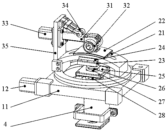
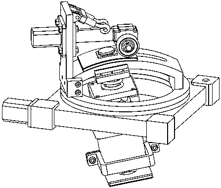
[0015] Specific implementation method: when in use, the spring telescopic rod (34) in the compression and transmission unit (3) is stretched out, and the worm gear device (31) and the compression wheel (32) are pressed against the arc-shaped slider (22) At the same time, fix the worm gear (31) and the servo motor (33) on the fixed plate (25) with bolts. During the working process, the servo motor (12) with the planetary reducer drives the fine-tuning turntable (11) to perform forward rotation and reverse rotation, so as to adjust the rotation angle of the camera. At the same time, the servo motor (33) drives the worm gear (31) to rotate the pressing wheel (32), and the arc-shaped slider (22) and the protrusion slider (23) are moved along the arc-shaped slide rail (21) through frictional force. ) to slide back and forth to drive the camera mount (4) to adjust the alignment direction of the camera.
PUM
 Abstract
Description
Claims
Application Information