A Test Method for Transmitting and Transmitting Beam Patterns of Ultra-sparse Antenna Arrays

A beam pattern, sparse antenna technology, applied in related application fields, can solve problems such as ground pattern testing, and achieve the effects of shortening test time, overcoming discomfort, and improving test accuracy

Active Publication Date: 2020-05-08
NO 54 INST OF CHINA ELECTRONICS SCI & TECH GRP
View PDF2 Cites 0 Cited by
  • Summary
  • Abstract
  • Description
  • Claims
  • Application Information

AI Technical Summary

Problems solved by technology

The present invention is more suitable for the far-field pattern test of super-sparse and distributed antenna arrays such as regional antenna arrays and networked radars, and overcomes the problem that such arrays cannot perform ground pattern tests

Method used


Image

  • A Test Method for Transmitting and Transmitting Beam Patterns of Ultra-sparse Antenna Arrays
  • A Test Method for Transmitting and Transmitting Beam Patterns of Ultra-sparse Antenna Arrays
  • A Test Method for Transmitting and Transmitting Beam Patterns of Ultra-sparse Antenna Arrays

Examples


Embodiment Construction

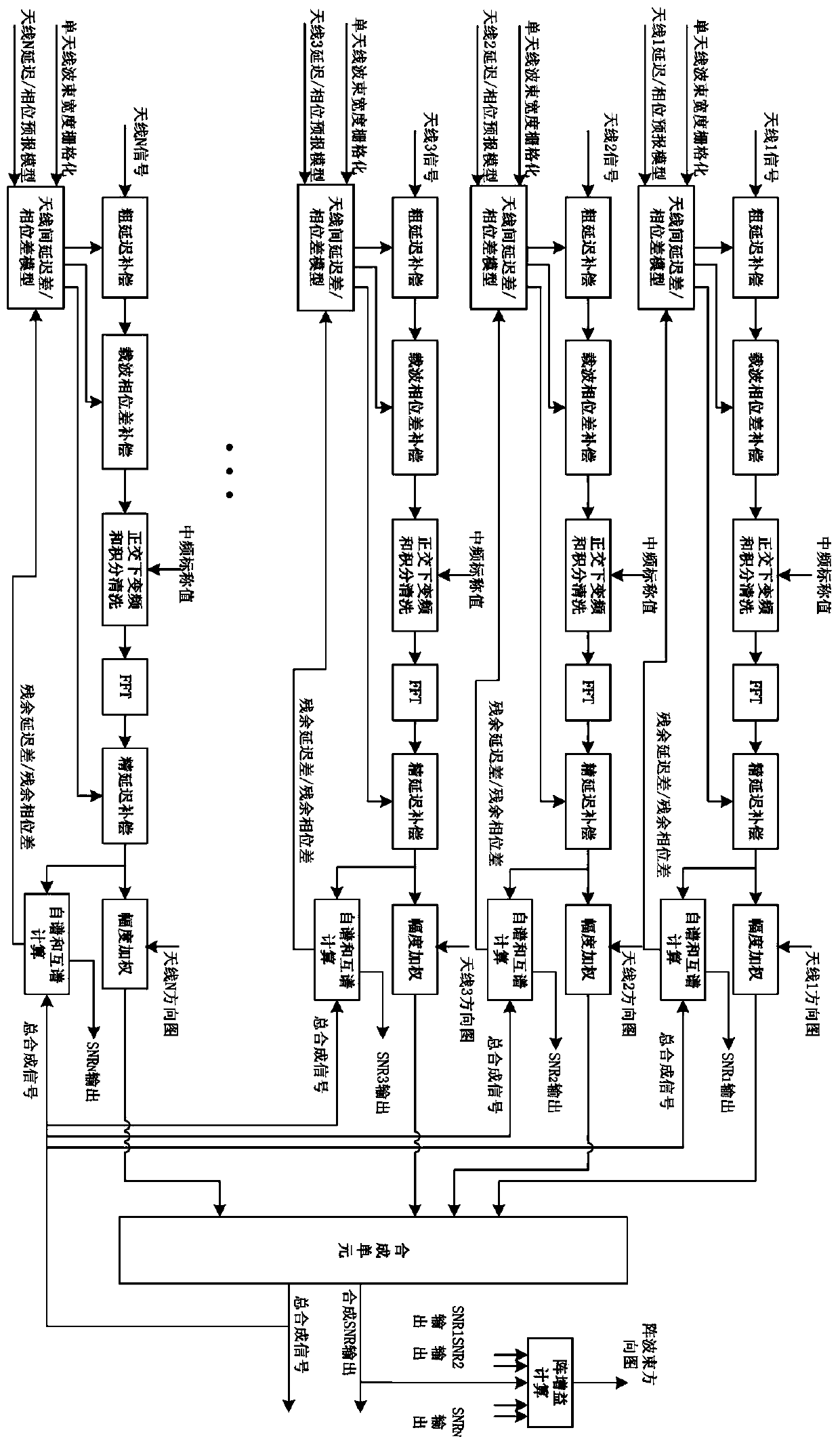
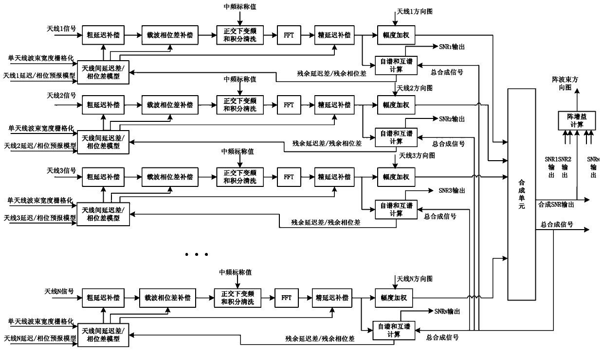
[0023] refer to figure 1 , the present invention will be further described.

[0024] A method for testing an ultra-sparse antenna array transceiver beam pattern, characterized in that it comprises the following steps:

[0025]①The inter-antenna delay / phase difference model unit selects antenna 1 as the reference antenna according to the delay / phase prediction model of antenna 1~antenna N input from the outside, and compares the delay / phase prediction model of antenna 1~antenna N with the reference antenna delay / phase The difference between the prediction model is obtained to obtain the corresponding inter-antenna delay difference / phase difference polynomial model of antenna 1~antenna N; according to the initial value of residual delay difference and residual phase difference output by the auto-spectrum and cross-spectrum calculation unit, each of antenna 1~antenna N The corresponding inter-antenna delay difference / phase difference polynomial models are corrected one by one, a...


PUM


Abstract

The invention discloses a method for testing a super-sparse antenna array transmitting and receiving beam pattern, which mainly solves the problem that the existing measurement method and system cannot test the ground pattern of the super-sparse antenna array. The present invention receives the echo signal of the same satellite through multiple antennas, and utilizes the FX correlation synthesizer to obtain the delay difference and phase difference between antennas as the zero value of the delay difference and phase difference between antennas; The incoming wave direction is rasterized, and the satellite signals received by each antenna are accurately compensated by using the corresponding delay difference and phase difference, so as to realize the test of the ultra-sparse antenna array sending and receiving pattern. The invention has the advantages of high delay / phase measurement precision, simple and reliable method, etc., and is more suitable for far-field pattern testing of super-sparse and distributed antenna arrays such as regional antenna arrays and networked radars.

Description

technical field [0001] The invention relates to antenna array signal synthesis technology in deep space measurement and control communication, distributed network radar coherent synthesis technology, interferometric data processing technology, etc., and is especially suitable for distributed arrays such as large-scale receiving antenna arrays and networked radars Antenna transmit and receive beam synthesis test, synthesis efficiency analysis and evaluation and other related application fields. Background technique [0002] In the deep space measurement and control communication system, due to the distance between the target of the deep space spacecraft and the earth station, ranging from tens of millions to hundreds of millions of kilometers, the received signal strength of the existing measurement and control communication equipment is very weak. It is an effective means to improve the transmit ERIP and receive signal SNR; in a networked radar system, the target detection, ...

Claims


Application Information

Patent Timeline
Patent Type & Authority Patents(China)
IPC IPC(8): G01R29/10G01S7/40
CPCG01R29/10G01S7/4004
Inventor 刘友永杨伟军
Owner NO 54 INST OF CHINA ELECTRONICS SCI & TECH GRP
Why Eureka
Try Eureka