
A method and device for antenna selection

An antenna selection and antenna technology, applied in the field of communication, can solve problems such as channel fading

Active Publication Date: 2020-11-03
COMBA TELECOM SYST CHINA LTD
View PDF4 Cites 0 Cited by
  • Summary
  • Abstract
  • Description
  • Claims
  • Application Information

AI Technical Summary

Problems solved by technology

However, channel fading occurs differently in different frequency bands formed by the antennas at the transmitting end and antennas at the receiving end. Therefore, the average received power of a receiving antenna with a large overall average power value on a certain frequency band may be smaller than the overall average power. The average received power of the receiving antenna with a small value in this frequency band

Method used


Image

  • A method and device for antenna selection
  • A method and device for antenna selection
  • A method and device for antenna selection

Examples


Embodiment Construction

[0023] In order to make the purpose, technical solutions, and beneficial effects of this application clearer and clearer, the following further describes this application in detail with reference to the accompanying drawings and embodiments. It should be understood that the specific embodiments described here are only used to explain the application, but not to limit the application.

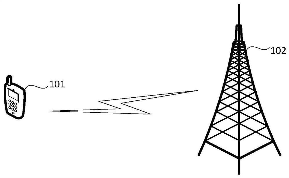
[0024] figure 1 Illustratively shows a schematic diagram of a system architecture to which the embodiments of this application are applicable, such as figure 1 Shown, including receiving end and sending end. In an optional implementation manner, the originating end may be the terminal device 101, and the receiving end may be the base station 102. In another optional implementation manner, the originating end may be the base station 102, and the receiving end may be the terminal device 101.

[0025] Terminal equipment can refer to User Equipment (UE), access terminal equipment, user unit, user statio...


PUM


Abstract

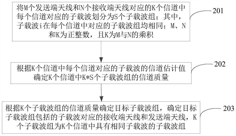
Embodiments of the application relate to the technical field of communications, particularly to a method and a device for selecting antennas. In the embodiments of the application, the subcarriers corresponding to each of the K channels corresponding to M transmitting end antennas and N receiving end antennas are divided into S subcarrier groups; the corresponding subcarrier groups of the subcarrier i in each channel are all the same; the channel quality of the K*S subcarrier groups in the K channels is determined according to the channel estimation values of the subcarriers corresponding to each of the K channels; a target subcarrier group and a receiving end antenna corresponding to the subcarrier included in the target subcarrier group are determined according to the channel quality ofthe K subcarrier groups, and the K subcarrier groups have the same subcarrier among the K channels. The receiving end may receive data on the subcarrier in the subcarrier group by using the receivingend antenna corresponding to the subcarrier group with better channel quality among the K subcarrier groups, thereby improving the channel capacity and minimizing the processing complexity of the receiver.

Description

Technical field [0001] The embodiments of the present application relate to the field of communication technologies, and in particular, to a method and device for antenna selection. Background technique [0002] With the rapid development of mobile communication technology, Multiple Input Multiple Output (MIMO) technology has received extensive attention as an effective way to efficiently utilize wireless spectrum resources. In order to reduce the complexity of MIMO system implementation, MOMI antenna selection technology is proposed. [0003] In the prior art, technicians determine the receiving antenna to be selected by measuring the average power value of each receiving antenna in the MOMI system. The larger the average power value of the receiving antenna, the better the signal receiving effect of the receiving antenna. However, channel fading occurs in different frequency bands on each channel formed by the transmitting end antenna and the receiving end antenna. Therefore, th...

Claims


Application Information

Patent Timeline
Patent Type & Authority Patents(China)
IPC IPC(8): H04B7/0413H04B7/06H04B7/08H04L5/00H04L25/02
CPCH04B7/0413H04B7/0608H04B7/0802H04L5/0003H04L5/0044H04L25/0204
Inventor 王一印刘重军付杰尉
Owner COMBA TELECOM SYST CHINA LTD
Learn More