
Linkage mechanism for foot massager

A linkage mechanism, massager technology, applied in massage auxiliary products, roller massage, instruments for compressing reflection points, etc., can solve the problems of few driving sources, limited massage effect, small change in clamping force, etc. Comfort, good massage effect, simple structure effect

Inactive Publication Date: 2018-07-24
HEFEI UNIV OF TECH
View PDF7 Cites 9 Cited by
  • Summary
  • Abstract
  • Description
  • Claims
  • Application Information

AI Technical Summary

Problems solved by technology

However, the foot rollers and instep rollers of this foot bath are not linked, and multiple driving sources are needed. Moreover, after the feet are put in place, the position of the instep rollers cannot move back and forth along the instep, and can only massage a small part of the instep area, massage effect is limited
In addition, since the rocker arm uses a spring to exert a downward force on the foot, after the foot is placed in place, the clamping force exerted by the foot changes little, and there is no time for the foot to relax during the massage
[0008] By studying the above five technical solutions, even if those skilled in the art combine them, they cannot obtain a satisfactory foot massager
Especially to make a foot massager with simple structure, few driving sources, massage soles and insteps at the same time, wide instep massage area, and compress and relax the feet during the massage process, the challenge is even greater

Method used


Image

  • Linkage mechanism for foot massager
  • Linkage mechanism for foot massager
  • Linkage mechanism for foot massager

Examples


Embodiment Construction

[0042] A detailed description will be given below in conjunction with the accompanying drawings.

[0043] In describing the present invention, it should be understood that the terms "center", "longitudinal", "transverse", "length", "width", "thickness", "upper", "lower", "front", " Orientation or position indicated by "back", "left", "right", "vertical", "horizontal", "top", "bottom", "inner", "outer", "clockwise", "counterclockwise", etc. The relationship is based on the orientation or positional relationship shown in the drawings, and is only for the convenience of describing the present invention and simplifying the description, rather than indicating or implying that the referred device or element must have a specific orientation, be constructed and operated in a specific orientation, therefore It should not be construed as a limitation of the present invention.

[0044] In addition, the terms "first" and "second" are used for descriptive purposes only, and cannot be inte...


PUM


Abstract

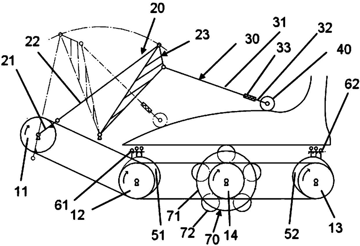
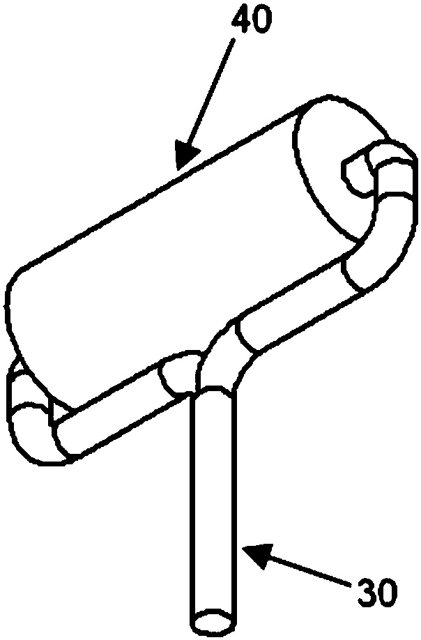
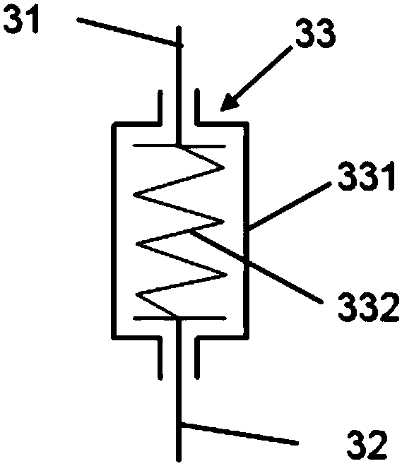
The invention relates to a linkage mechanism for a foot massager. The linkage mechanism comprises a first wheel disc, a second wheel disc, a crank-rocker mechanism, a massage stick and a first cam, the first wheel disc, the second wheel disc and the crank-rocker mechanism can rotate, the massage stick is used for massaging foot dorsum, the first cam rotates along with the second wheel disc to drive a first sole massage plate to move along a straight line, the second wheel disc and the first wheel disc are directly or indirectly linked each other in the rotating aspect, one end of a crank of the crank-rocker mechanism is fixedly connected with the first wheel disc, so that the crank circumferentially moves along with the first wheel disc, and one end of the massage stick is rotatably connected on a rocker of the crank-rocker mechanism, so that the other end of the rocker massages the foot dorsum backwards and forwards under driving of the rocker. A plurality of positions of the sole andthe foot dorsum can be comfortably and effectively massaged in a simple transmission manner, the massage stick not only can massage the foot dorsum, but body feet are suitably positioned, downward pressing action force is applied to the feet, and manual downward stepping force application or the complicated process of using a foot fixing device is omitted.

Description

technical field [0001] The invention relates to the field of physical therapy devices, in particular to a linkage mechanism for a foot massager. Background technique [0002] Due to historical reasons, the development of the rehabilitation industry in my country is later than that in developed countries. However, under the attention and promotion of the Chinese government and relevant departments, some achievements have been made by drawing on the development models and ideas of the rehabilitation industry of developed countries in the world. With the steady progress of economic development and the period of population transition, my country is facing problems such as high work pressure and population aging. The foot massager can effectively help people relax and exercise. [0003] At this stage, most of the foot massagers on the market only repeatedly massage the sole of the foot, because the instep is not massaged, and it is necessary to artificially apply downward force...

Claims


Application Information

Patent Timeline
IPC IPC(8): A61H15/00A61H39/04
CPCA61H15/0078A61H39/04A61H2015/0014A61H2015/0028A61H2205/12A61H2205/125
Inventor 赵萍陈文秀赵康荏陈浩东王一帆
Owner HEFEI UNIV OF TECH
Learn More