
Nephrology department clinical hematodialysis switching device

A technology of hemodialysis and conversion device, applied in the field of medical devices, can solve the problems of inconvenience of use, inconvenience to move, inability to sterilize medical aids, etc., and achieve the effect of convenient use and convenient sterilization

Inactive Publication Date: 2018-07-24
AFFILIATED HOSPITAL OF WEIFANG MEDICAL UNIV
View PDF4 Cites 4 Cited by
  • Summary
  • Abstract
  • Description
  • Claims
  • Application Information

AI Technical Summary

Problems solved by technology

The hemodialysis switching device for nephrology of the present invention comprises a hemodialysis device main body, a console is provided on the hemodialysis device main body, a display base is provided on the console, a support frame is provided on the display base, and a display screen is provided on the support frame. There is a data display screen on the front side of the imaging device, a power switch on the lower side of the data display screen, a conversion knob slot on the front side of the display base, a conversion knob in the conversion knob slot, and a switch knob on the conversion knob. Rotary shaft, with a rotary valve on the rotary shaft, a frequency modulation slot on the right side of the conversion knob slot, an adjustment slider in the frequency modulation slot, a control area on the front side of the console, and function buttons and selection buttons in the control area , there is a device switch on the right side of the console, but the hemodialysis conversion device for nephrology is inconvenient to move, the height of the dialysis machine cannot be adjusted, and the medical auxiliary tools cannot be sterilized, so it is inconvenient to use

Method used


Image

  • Nephrology department clinical hematodialysis switching device
  • Nephrology department clinical hematodialysis switching device

Examples


Embodiment Construction

[0014] The following will clearly and completely describe the technical solutions in the embodiments of the present invention with reference to the accompanying drawings in the embodiments of the present invention. Obviously, the described embodiments are only some, not all, embodiments of the present invention. Based on the embodiments of the present invention, all other embodiments obtained by persons of ordinary skill in the art without making creative efforts belong to the protection scope of the present invention.

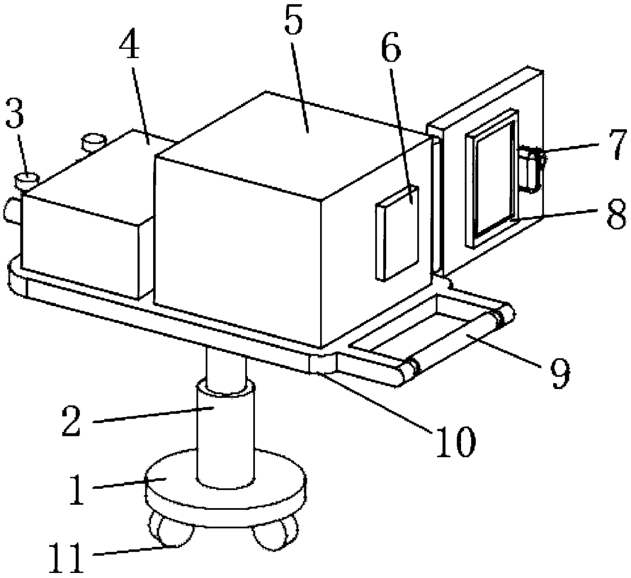
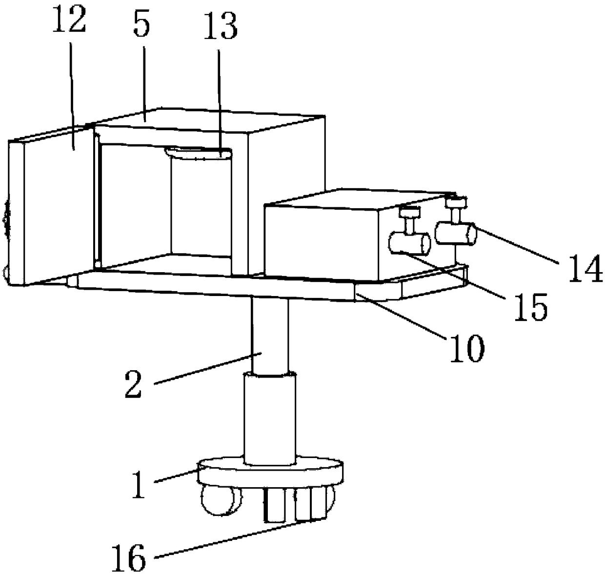
[0015] see Figure 1-2 , the present invention provides a technical solution: a hemodialysis conversion device for clinical nephrology, comprising a base plate 1, one end of the upper surface of the base plate 1 is provided with an electric telescopic rod 2, and the upper surface of the electric telescopic rod 2 is provided with a console 10, The upper surface of the console 10 is provided with a hemodialysis machine 4, and the height of the hemodialysis machi...


PUM


Abstract

The invention discloses a nephrology department clinical hematodialysis switching device which comprises a bottom plate. An electric telescopic rod is arranged at one end of the upper surface of the bottom plate. An operation table is arranged on the upper surface of the electric telescopic rod. A hematodialysis machine is arranged on the upper surface of the operation table. The side face of thehematodialysis machine is provided with a fluid inlet pipe and a fluid outlet pipe. A medical disinfecting box is arranged at the other end of the upper surface of the bottom plate. A control switch group is arranged on the right side face of the medical disinfecting box. A hinge is arranged at one end of the rear side face of the medical disinfecting box. The medical disinfecting box is connectedwith a closing door through the hinge. The nephrology department clinical hematodialysis switching device can be conveniently moved and braked through armrests, universal wheels and brakes, the height of the hematodialysis machine can be conveniently adjusted through the electric telescopic rod, medical auxiliary tools can be conveniently disinfected through the medical disinfecting box, and thehematodialysis switching device is convenient to use and suitable for use and popularization.

Description

technical field [0001] The invention relates to the technical field of medical devices, in particular to a hemodialysis conversion device for clinical use in nephrology. Background technique [0002] When people are treating diseases, they need to treat the liquid. By flowing the body fluid out of the body, in a device composed of countless roots, the liquid and the electrolyte solution containing the concentration phase of the body are inside and outside the roots, and the substances are exchanged through convection. , to remove waste, electrolytes and acids in the body; at the same time remove excess water in the body, and the whole process of transfusing the purified liquid into a liquid, so the device needs to be used in combination with multiple devices, making the work complicated. In the long run, Greatly increased the difficulty of people's work. [0003] For example, the patent application publication number CN104707195A discloses a hemodialysis conversion device f...

Claims


Application Information

Patent Timeline
IPC IPC(8): A61M1/16A61L2/10
CPCA61L2/10A61L2202/24A61M1/1621A61M2202/0413A61M2202/0021
Inventor 邱书娟
Owner AFFILIATED HOSPITAL OF WEIFANG MEDICAL UNIV
Learn More