Cutting device for wood processing

A cutting device and wood technology, applied in the field of wood processing, can solve problems such as poor wood fixing effect, achieve good fixing effect, convenient use, and avoid shaking

Pending Publication Date: 2018-07-24
JIANGSU MINGLE FLOOR
15 Cites 2 Cited by

AI-Extracted Technical Summary

Problems solved by technology

[0005] Aiming at the deficiencies of the prior art, the present invention provides a cutting device for wood processing, which has the a...

Abstract

The invention discloses a cutting device for wood processing. The cutting device for wood processing comprises a bottom box; an electric telescopic rod is fixedly connected to the left side of the topof the bottom box; a supporting plate is fixedly connected to the top of the electric telescopic rod; a fixed rod is arranged on the right side of the bottom of the supporting plate; a first motor isfixedly connected to the bottom of the fixed rod; a cutting disc is fixedly connected to the output end of the first motor; and a baffle is fixedly connected to the bottom of the inner wall of the bottom box. Through cooperative use of a rotary plate, a cylinder, a connecting rod, a first pressing rod, a sliding rod, a second pressing rod, a pressing block, a movable rod, a third sliding chute, asecond motor and the baffle, the problem of a poor wood fixing effect of an existing wood cutting device is solved, the wood cutting device has the advantage of good wood fixing effect, the situationthat wood is not smoothly cut due to shaking in the cutting process is avoided, users use the cutting device conveniently, and practicability of the wood cutting device is improved.

Application Domain

Sawing componentsCircular saws

Technology Topic

Electric machineryWood processing +3

Image

  • Cutting device for wood processing
  • Cutting device for wood processing

Examples

  • Experimental program(1)

Example Embodiment

[0019] The following will clearly and completely describe the technical solutions in the embodiments of the present invention with reference to the accompanying drawings in the embodiments of the present invention. Obviously, the described embodiments are only some, not all, embodiments of the present invention. Based on the embodiments of the present invention, all other embodiments obtained by persons of ordinary skill in the art without making creative efforts belong to the protection scope of the present invention.
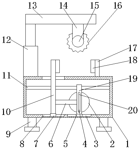
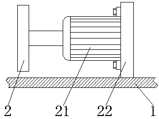
[0020] see Figure 1-2 , a cutting device for wood processing, comprising a bottom box 1, the four corners of the bottom of the base 1 are fixedly connected with a support column 9, the bottom of the support column 9 is fixedly connected with an anti-slip pad, and the bottom of the anti-slip pad is provided with an anti-skid pattern, through the anti-skid The setting of the pad improves the stability of the wood cutting device when it is working, and avoids the situation that the wood cutting device slips during work due to the lack of anti-skid devices. The left side of the top of the bottom box 1 is fixedly connected with an electric telescopic rod 12 The top of the electric telescopic rod 12 is fixedly connected with a support plate 13, the right side of the bottom of the support plate 13 is provided with a fixed rod 14, the bottom of the fixed rod 14 is fixedly connected with a first motor 15, and the output end of the first motor 15 is fixedly connected with a Cutting sheet 16, the bottom of bottom box 1 inner wall is fixedly connected with baffle plate 22, and the front of baffle plate 22 is provided with second motor 21, and the bottom and top of second motor 21 are all fixedly connected with fixed piece, and the backside of fixed piece It is fixedly connected with the front of the baffle plate 22 through bolts, and the stability of the second motor 21 is improved through the setting of the fixing plate and the bolts, and the instability of the second motor 21 during operation is avoided due to the lack of fixing devices , the output end of the second motor 21 is fixedly connected with the turntable 2, the front of the turntable 2 is fixedly connected with the cylinder 4, the surface of the cylinder 4 is provided with the movable rod 19, the bottom of the movable rod 19 is fixedly connected with the first slider 5, and the bottom The right side of the bottom of the inner wall of the box 1 is provided with a first chute 3 used in conjunction with the first slider 5, through the setting of the first slider 5 and the first chute 3, the stability when the movable rod 19 moves is improved, Avoided the shaking situation when movable rod 19 moves, the back side of movable rod 19 is slidably connected with slide rod 11, and the both sides of slide rod 11 are all fixedly connected with the inner wall of bottom box 1, and the front of movable rod 19 is provided with cylinder. 4 Cooperate with the third chute 20, the left side of the movable rod 19 is fixedly connected with the connecting rod 6, the left side of the connecting rod 6 is fixedly connected with the first pressing rod 10, and the bottom of the first pressing rod 10 is fixedly connected with the second sliding Block 7, the left side of the bottom of the inner wall of the bottom box 1 is provided with a second chute 8 used in conjunction with the second slide block 7, through the setting of the second slide block 7 and the second chute 8, the first pressure bar 10 is improved. Stability during movement avoids shaking when the first pressure rod 10 moves, the back side of the first pressure rod 10 is slidingly connected with the surface of the slide rod 11, and the top of the first pressure rod 10 penetrates to the bottom of the bottom box 1 The top, the right side of the top of the bottom box 1 is fixedly connected with a second pressure rod 17, and the left side of the second pressure rod 17 and the right side of the first pressure rod 10 are fixedly connected with a pressure block 18.
[0021] When in use, the user starts the second motor 21 to work, the second motor 21 works to drive the turntable 2 to rotate, the turntable 2 rotates to drive the cylinder 4 to rotate, and the cylinder 4 rotates through the third chute 20 to drive the movable rod 19 on the surface of the slide rod 11 Move, the moving rod 19 moves to drive the connecting rod 6 to move, and the moving of the connecting rod 6 drives the first pressing rod 10 to move on the surface of the slide bar 11, under the cooperation of the first pressing rod 10, the second pressing rod 17 and the pressing block 18 Fixing the wood achieves the advantage of good wood fixing effect.
[0022] In summary, the wood cutting device, through the turntable 2, the cylinder 4, the connecting rod 6, the first pressing rod 10, the sliding rod 11, the second pressing rod 17, the pressing block 18, the movable rod 19, the third chute 20 1. The cooperative use of the second motor 21 and the baffle plate 22 solves the problem that the existing wood cutting device has a bad fixing effect on the wood.
[0023] Although the embodiments of the present invention have been shown and described, those skilled in the art can understand that various changes, modifications and substitutions can be made to these embodiments without departing from the principle and spirit of the present invention. and modifications, the scope of the invention is defined by the appended claims and their equivalents.

PUM

no PUM

Description & Claims & Application Information

We can also present the details of the Description, Claims and Application information to help users get a comprehensive understanding of the technical details of the patent, such as background art, summary of invention, brief description of drawings, description of embodiments, and other original content. On the other hand, users can also determine the specific scope of protection of the technology through the list of claims; as well as understand the changes in the life cycle of the technology with the presentation of the patent timeline. Login to view more.

Similar technology patents

Silicone pad transferring and fitting device

Owner:GUANGDONG XG INTELLIGENT SYST CO LTD

A single-port laparoscopic instrument system for V-NOTES surgery

Owner:SHANGHAI FIRST MATERNITY & INFANT HOSPITAL

Classification and recommendation of technical efficacy words

  • Good fixed effect
  • easy to use

Auxiliary supporting frame for ophthalmology department doctor operation

ActiveCN108938301AGood fixed effectAvoid affecting the results of surgery
Owner:THE THIRD AFFILIATED HOSPITAL OF XINXIANG MEDICAL UNIV

Drawing board for environmental art design

InactiveCN109484063AGood fixed effectImprove drawing efficiency
Owner:安陆风常建筑景观规划设计有限公司
Why Eureka
Try Eureka