
Hoisting height lifting device for crane

A technology of raising height and vertical frame, which is applied in the directions of transportation and packaging, load hanging components, support structures, etc., can solve the problems of the requirement of lifting height, reduce work efficiency, and cannot be adjusted, so as to achieve convenient and fast adjustment and improve use. range, the effect of increasing the lifting height

Pending Publication Date: 2018-07-24
苏州库力铁重工有限公司
View PDF0 Cites 0 Cited by
  • Summary
  • Abstract
  • Description
  • Claims
  • Application Information

AI Technical Summary

Problems solved by technology

However, due to the determination of the position of the main beam, the position of the electric hoist installed on the main beam is also determined, so the lifting height is also determined, but some have requirements for the lifting height of heavy objects, which need to be based on the existing lifting height At this time, the main beam needs to be reinstalled, which is time-consuming and laborious, and the work efficiency is low; in addition, in order to stop the movement of the electric hoist, a stop plate is installed on the main beam, and the stop plate is welded on the main beam It is not adjustable. If you need to change the stroke of the electric hoist, you need to cut off the stop plate and re-make and weld it, which not only increases the production cost, wastes manpower and material resources, but also reduces work efficiency.

Method used


Image

  • Hoisting height lifting device for crane
  • Hoisting height lifting device for crane
  • Hoisting height lifting device for crane

Examples


Embodiment Construction

[0017] The present invention will now be further described in detail in conjunction with the accompanying drawings and embodiments. These drawings are all simplified schematic diagrams, only illustrating the basic structure of the present invention in a schematic manner, so it only shows the composition related to the present invention.

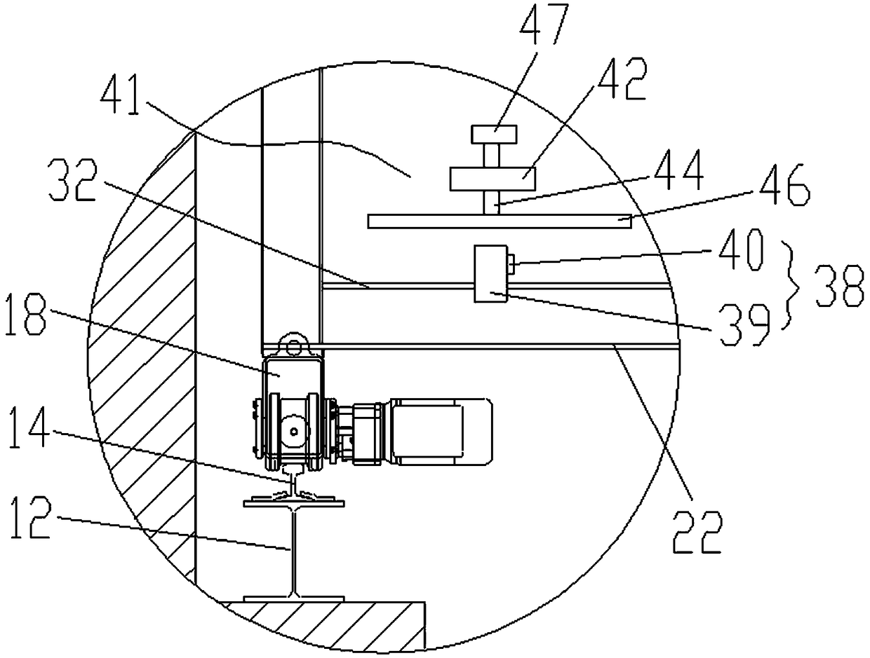
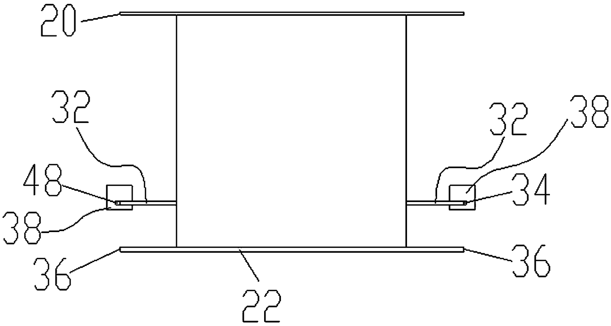
[0018] Such as Figure 1-Figure 3 As shown, a hoisting height raising device for hoisting includes two vertical stands oppositely arranged on the left and right, load-carrying beams installed on the two vertical stands, and each vertical stand includes two vertical plates 10 arranged symmetrically front and back, connecting The I-shaped plate 12 of the two vertical plates 10 and the I-shaped track 14 installed on the I-shaped plate 12, the load-bearing beam includes a main beam 16, two end beams 18 respectively fixed on both sides of the bottom end of the main beam 16, and the main beam 16 comprises a top plate 20, a bottom plate 22, a front ...


PUM


Abstract

The invention relates to a hoisting height lifting device for a crane. The hoisting height lifting device comprises two vertical frames and a bearing beam, wherein the two vertical frames are in left-right opposite arrangement; the bearing beam is arranged on the two vertical frames; each vertical frame comprises two vertical plates which are in back-and-forth symmetric arrangement, an I-shaped plate connected with the two vertical plates and an I-shaped track arranged on the I-shaped plate; the bearing beam comprises a main beam and two end beams which are respectively and fixedly arranged attwo sides of the bottom end of the main beam; the main beam comprises a top plate, a bottom plate, a front side plate, a rear side plate, a left side plate and a right side plate; horizontal plates are fixedly arranged on the outer surfaces of the front side plate and the rear side plate; first outer side surfaces of the two horizontal plates are respectively flush with two second outer side surfaces of the bottom plate. According to the hoisting height lifting device disclosed by the invention, the distance from a weight to limit lifting height of a lifting hook is increased, the hoisting height of the crane is increased, an indoor using range of the crane is increased, the position of the main beam has no need to be adjusted, and the use is very convenient and quick.

Description

technical field [0001] The invention relates to a hoisting device, in particular to a hoisting height raising device for hoisting. Background technique [0002] Lifting equipment is widely used in industrial production, storage, and docks. However, due to the determination of the position of the main beam, the position of the electric hoist installed on the main beam is also determined, so the lifting height is also determined, but some have requirements for the lifting height of heavy objects, which need to be based on the existing lifting height At this time, the main beam needs to be reinstalled, which is time-consuming and laborious, and the work efficiency is low; in addition, in order to stop the movement of the electric hoist, a stop plate is installed on the main beam, and the stop plate is welded on the main beam It cannot be adjusted. If the stroke of the electric hoist needs to be changed, the stop plate needs to be cut off and re-made and welded, which not only ...

Claims


Application Information

Patent Timeline
IPC IPC(8): B66C6/00B66C7/16
CPCB66C6/00B66C7/16
Inventor 沈青
Owner 苏州库力铁重工有限公司
Learn More